
Ostomy instrument

An instrument and stoma technology, which is applied to heating surgical instruments, surgical forceps, etc., can solve the problems of increased incidence of thrombosis and difficulty in performing ostomy again, and achieves the effect of avoiding easy retraction and difficult retraction

Active Publication Date: 2017-01-04
LIFETECH SCIENTIFIC (SHENZHEN) CO LTD
View PDF9 Cites 5 Cited by
  • Summary
  • Abstract
  • Description
  • Claims
  • Application Information

AI Technical Summary

Problems solved by technology

Although the stoma stent prevents stoma retraction, the incidence of channel embolism and thrombosis increases accordingly after the stoma stent is implanted
Also, after a blockage, the presence of the stent makes it difficult to perform another ostomy
In addition, in the field of stoma, the above-mentioned defects also exist for stomas of other tissues such as the pericardium, stomach, and colon.

Method used


Image

  • Ostomy instrument
  • Ostomy instrument
  • Ostomy instrument

Examples


no. 1 example

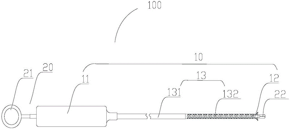
[0044] figure 1It is a schematic structural diagram of an ostomy instrument 100 for stoma an atrial septum according to the first embodiment of the present invention. The ostomy instrument 100 includes a hollow cutting device 10 and a grabbing device 20 for grabbing a part of atrial septal tissue that needs to be cut before forming an stoma on the atrial septum. The grabbing device 20 passes through the cutting device 10 .

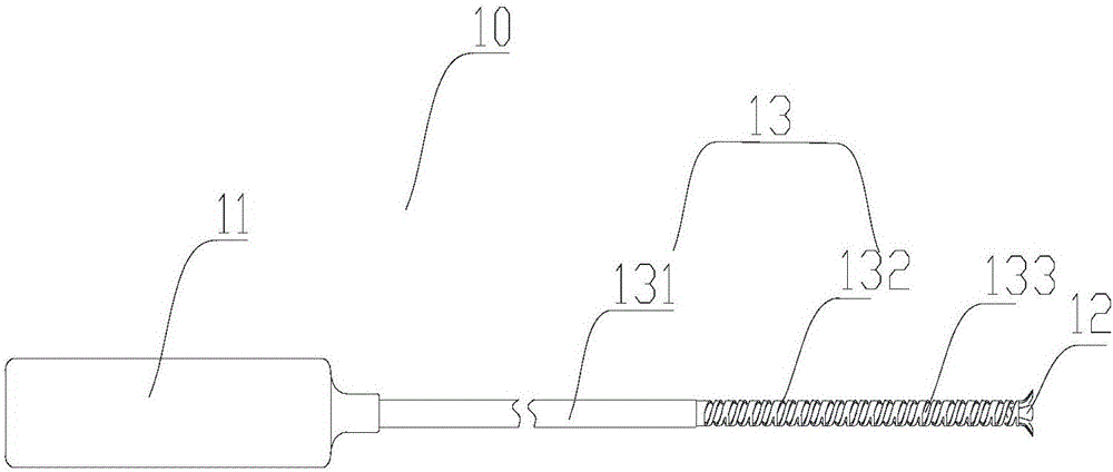
[0045] see figure 2 , the cutting device 10 includes a first control part 11 , a cutting part 12 and a first support part 13 which is tubular and deflectable. The first support part 13 is disposed between the first control part 11 and the cutting part 12 . During the stoma, the first control part 11 is closer to the operator than the cutting part 12, and is used to control the first supporting part 13 to drive the cutting part 12 to rotate axially around the first supporting part 13. The first supporting portion 13 accommodates the partial grabbing de...

no. 2 example

[0060] Such as Figures 13 to 1 As shown in 5, the atrial septostomy instrument 200 of the second embodiment of the present invention is substantially the same as the ostomy instrument 100, and it includes a cutting device 10a and a grasping device 22a. The cutting device 10a includes a first control part 11a, a cutting part 12a and a first supporting part 13a. The cutting section 12a includes three cutting units 14a. The difference between the ostomy appliance 200 and the ostomy appliance 100 is that the cutting unit 14a is an electrode probe that can receive high-frequency current, and the first control part 11a is an electrode probe that can transmit high-frequency current to the electrode probe. High frequency current generator. The three cutting units 14a are uniformly arranged on the distal end surface of the first supporting portion 13a in the circumferential direction. The high-frequency current generating device is connected with the electrode probes through wires ...


PUM


Abstract

The invention relates to an ostomy instrument. The ostomy instrument comprises a cutting device and a grabbing device. The cutting device sleeves the grabbing device and comprises a tubular first supporting portion and a rotary cutting portion, and the cutting portion is connected with the first supporting portion which slidably sleeves the grabbing device. The cutting portion comprises at least one cutting unit which comprises a connection end, a free end and a connection part, the connection end is connected with the first supporting portion, the connection part is connected between the connection end and the free end, the connection part extends in a direction away from the first supporting portion and extends outwards radially, and the connection part is capable of retracting in a direction close to the center axis of the first supporting portion. By application of the ostomy instrument which is a septostomy instrument to septostomy, simplicity in positioning, convenience in ostomy, large stoma diameter and less proneness to resilience of peripheral stoma tissues are realized.

Description

technical field [0001] The invention relates to the field of medical devices, in particular to an ostomy device. Background technique [0002] In the blood circulation system of the human body, the venous blood returning from the superior and inferior vena cava to the right atrium enters the right ventricle through the tricuspid valve, and then enters the pulmonary circulation. The mitral valve enters the left ventricle and then supplies the body through the aorta. Under normal circumstances, the left atrium (or left ventricle) and the right atrium (or right ventricle) are completely isolated from each other by the interatrial septum (or interventricular septum). However, in some specific cases, for example, for patients with advanced pulmonary hypertension, it is necessary to create an opening in the atrial septum so that blood from the left and right atrium can communicate with each other to balance the pressure of the left and right atrium, or to increase blood pressure....

Claims


Application Information

Patent Timeline
Patent Type & Authority Applications(China)
IPC IPC(8): A61B18/12
CPCA61B17/295A61B18/12
Inventor 陈文俊庄少春
Owner LIFETECH SCIENTIFIC (SHENZHEN) CO LTD
Learn More