
Microwave induction light-controlled LED lighting lamp

A technology of LED lighting and microwave induction, which is applied in the direction of lighting devices, light sources, electric light sources, etc., can solve the problems of energy saving and environmental protection, energy waste, and difficulty in achieving suitable illuminance, and achieve the effects of saving electric energy and protecting eyesight

Active Publication Date: 2016-12-21
SUZHOU KUN SHI LAI ILLUMINATION TECH
View PDF7 Cites 2 Cited by
  • Summary
  • Abstract
  • Description
  • Claims
  • Application Information

AI Technical Summary

Problems solved by technology

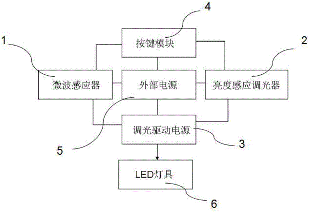
[0004] In order to overcome the disadvantages that traditional LED lighting lamps are difficult to achieve suitable illuminance, and there is energy waste that cannot save energy and protect the environment, the present invention provides a microwave induction light control LED lighting lamp, including a microwave sensor, a brightness induction dimmer, a dimming Drive power supply, button module, external power supply and LED lamps, the microwave sensor, brightness induction dimmer, button module and dimming drive power supply are all connected to an external power supply, and the external power supply is used for the LED lighting To provide energy, the microwave sensor and the brightness sensing dimmer are both connected to the button module, the button module is used to control the switch of the LED lighting lamp, the microwave sensor and the brightness sensing dimmer are both It is connected with the dimming driving power supply, the dimming driving power supply is connected with the LED lamp, and the dimming driving power supply can adjust the brightness of the LED lighting lamp

Method used


Image

  • Microwave induction light-controlled LED lighting lamp

Examples


Embodiment 1

[0015] This embodiment provides a microwave induction light-controlled LED lighting lamp, including a microwave sensor, a brightness induction dimmer, a dimming drive power supply, a key module, an external power supply, and an LED lamp. The device, the button module and the dimming driving power supply are all connected to an external power supply, and the external power supply is used to provide energy for the LED lighting lamp, and the microwave sensor and the brightness sensing dimmer are all connected to the button module , the button module is used to control the switch of the LED lighting lamp, the microwave sensor and the brightness sensing dimmer are both connected to the dimming driving power supply, and the dimming driving power supply is connected to the LED lamp, The dimming driving power supply can adjust the brightness of the LED lighting lamp.

[0016] The microwave sensor is connected with the dimming drive power supply and installed on the top of the room. T...

Embodiment 2

[0022] This embodiment provides a microwave induction light-controlled LED lighting lamp, including a microwave sensor, a brightness induction dimmer, a dimming drive power supply, a key module, an external power supply, and an LED lamp. The device, the button module and the dimming driving power supply are all connected to an external power supply, and the external power supply is used to provide energy for the LED lighting lamp, and the microwave sensor and the brightness sensing dimmer are all connected to the button module , the button module is used to control the switch of the LED lighting lamp, the microwave sensor and the brightness sensing dimmer are both connected to the dimming driving power supply, and the dimming driving power supply is connected to the LED lamp, The dimming driving power supply can adjust the brightness of the LED lighting lamp.

[0023] The microwave sensor is connected with the dimming drive power supply and installed on the top of the room. T...

Embodiment 3

[0029] Such as figure 1 As shown, this embodiment provides a microwave induction light-controlled LED lighting lamp, including a microwave sensor 1, a brightness induction dimmer 2, a dimming drive power supply 3, a key module 4, an external power supply 5 and an LED lamp 6. The microwave sensor 1, the brightness sensing dimmer 2, the button module 4 and the dimming drive power supply 3 are all connected to an external power supply 5, and the external power supply 5 is used to provide energy for the LED lighting lamp, and the microwave induction Both the sensor 1 and the brightness sensing dimmer 2 are connected to the button module 4, and the button module 4 is used to control the switch of the LED lighting lamp, and the microwave sensor 1 and the brightness sensing dimmer 2 are connected to each other. The dimming driving power supply 3 is connected, the dimming driving power supply 3 is connected with the LED lamp 6, and the dimming driving power supply 3 can adjust the bri...


PUM


Abstract

The invention discloses a microwave induction light-controlled LED lighting lamp. The microwave induction light-controlled LED lighting lamp comprises a microwave inductor, a brightness induction dimmer, a dimming driving power source, a key module, an external power source and an LED lamp; the microwave inductor, the brightness induction dimmer, the key module and the dimming driving power source are all connected with the external power source; the external power source is used for supplying energy to the LED lighting lamp; the microwave inductor and the brightness induction dimmer are both connected with the key module; the key module is used for controlling the on-off of the LED lighting lamp; the microwave inductor and the brightness induction dimmer are both connected with the dimming driving power source; the dimming driving power source is connected with the LED lamp; and the dimming driving power source can adjust the brightness of the LED lighting lamp. The microwave induction light-controlled LED lighting lamp of the invention has the advantages of high efficiency, energy-saving performance, high microwave induction sensitivity and wide application range, and can maintain a constant light illuminance in an indoor environment and can effectively protect the eyes of people.

Description

technical field [0001] The invention relates to the field of LED lighting lamps, in particular to a microwave induction light control LED lighting lamp. Background technique [0002] LED lighting is more and more widely used in our daily life. It has the following characteristics: high purity, bright and rich colors; super long life, its actual life is more than 50,000 hours, which is several times or even higher than that of general light sources. Dozens of times; there is no mercury in the light source, and the beam does not contain ultraviolet light, because LED is a solid light source, green and environmentally friendly, especially suitable for professional places such as perfume shops, jewelry stores, museums, art galleries, etc., which can meet the lighting requirements of their display products Special requirements; solid light, good shock resistance, firm and reliable. Therefore, LED lighting has the advantages of energy saving, environmental protection, and long li...

Claims


Application Information

Patent Timeline
IPC IPC(8): H05B33/08H05B44/00
CPCH05B45/10Y02B20/30
Inventor 李芝妹陈良林成渊林成超
Owner SUZHOU KUN SHI LAI ILLUMINATION TECH
Learn More