Eureka AIR delivers breakthrough ideas for toughest innovation challenges, trusted by R&D personnel around the world.

Constant-temperature water discharging assembly facilitating mounting

A water outlet component and constant temperature technology, applied in the field of sanitary ware, can solve the problems of the temperature limiting function, the failure of the constant temperature function, and the hidden danger of users' safety.

Active Publication Date: 2016-12-21
KAIPING HIMARK SANITARY WARE & BATHROOM
View PDF8 Cites 1 Cited by
  • Summary
  • Abstract
  • Description
  • Claims
  • Application Information

AI Technical Summary

Problems solved by technology

[0002] Conventional constant temperature water outlet components have hot water on the left and cold water on the right, but in the actual installation process of water and electricity, the pipes in many homes and bathing centers are buried upside down, with cold water on the left and hot water on the right, which makes it impossible to install a constant temperature The constant temperature function of the water outlet component will be invalid; and the lock of the commonly used constant temperature water outlet component at the highest set temperature is usually only completed by an elastic button. When the elastic button loses its elasticity after long-term use, the temperature limit function of the constant temperature water outlet component There are problems, and there are potential safety hazards for users

Method used


Image

  • Constant-temperature water discharging assembly facilitating mounting
  • Constant-temperature water discharging assembly facilitating mounting
  • Constant-temperature water discharging assembly facilitating mounting

Examples


Embodiment Construction

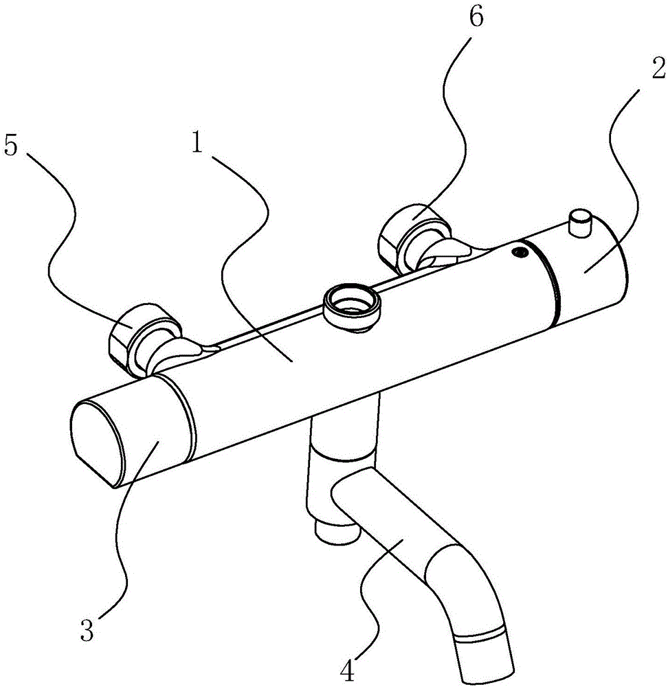
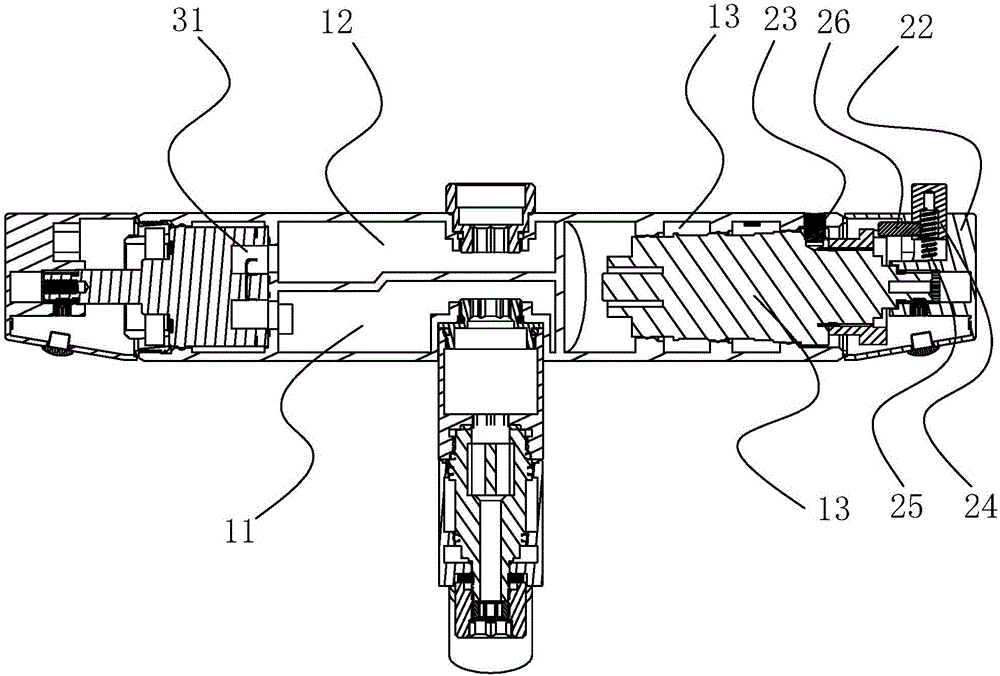
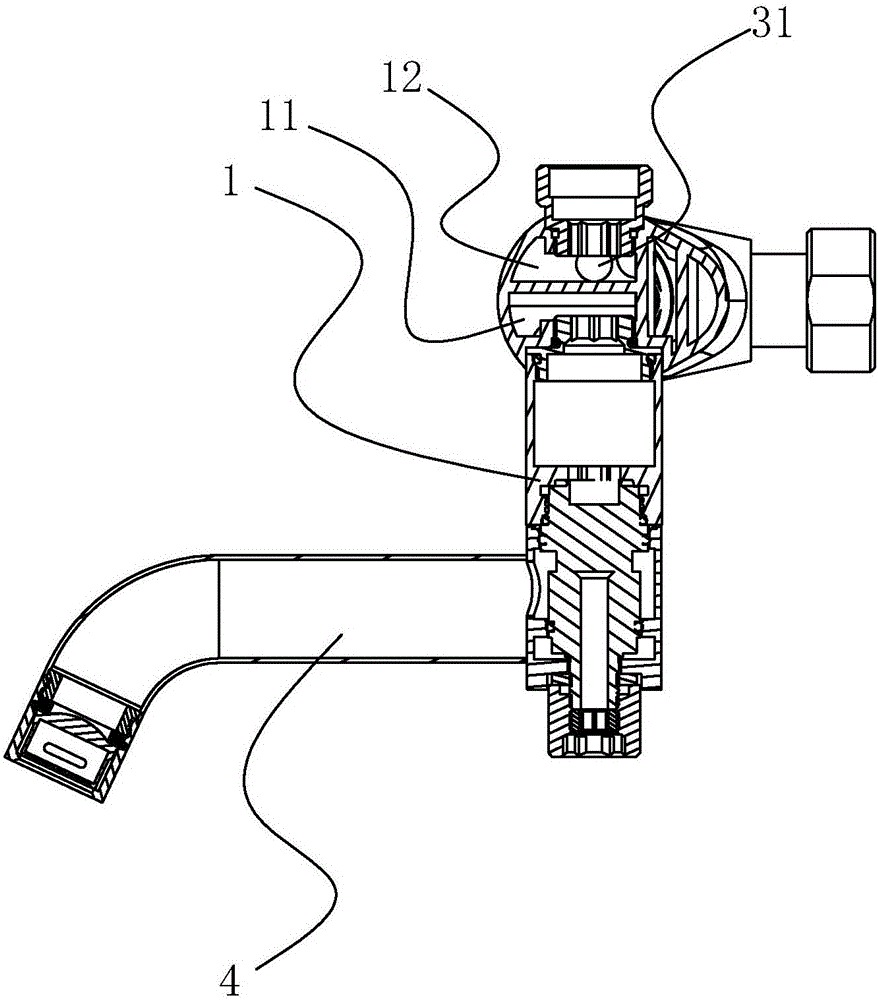
[0017] Such as Figure 1-Figure 3 As shown, an easy-to-install constant temperature water outlet assembly includes a water storage part 1, a thermostatic control valve 2 arranged on the right side of the water storage part 1, a water exchange valve 3 arranged on the left side of the water storage part 1, and a water The water outlet 4 and the shower head on the part 1, the right end of the water storage part 1 is provided with a hot water inlet 6, the left end of the water storage part 1 is provided with a cold water inlet 5, the water outlet 4 and the shower head are arranged on the hot water Between the water inlet 6 and the cold water inlet 5; in the water storage part 1, a first inner chamber 11 connected to the water outlet 4 and a second inner chamber 12 connected to the shower head are arranged in isolation, and the water exchange valve 3 is provided with a Connecting pipe 31, one end of the connecting pipe 31 is connected to the cold water inlet 5, and the other end of...


PUM


Abstract

The invention discloses a constant-temperature water discharging assembly facilitating mounting. The constant-temperature water discharging assembly comprises a water storage part, a constant-temperature control valve, a water changing valve, a water discharging nozzle and a shower head, wherein a hot water inlet is formed in the right end of the water storage part; a cold water inlet is formed in the left end of the water storage part; the water discharging nozzle and the shower head are arranged between the hot water inlet and the cold water inlet; a first inner cavity and a second inner cavity are formed in the water storage part; a connection pipe is arranged in the water changing valve; and the connection pipe and the cold water inlet relatively slide left and right through a sliding chute. The constant-temperature water discharging assembly is designed to enable cold water to enter from the left side and enable hot water to enter from the right side, so that the problem that the constant-temperature water discharging assembly can be still mounted even if a water entering pipeline is installed upside down is solved. The constant-temperature water discharging assembly can precisely adjust the temperature and save energy and water, can avoid the phenomenon that the water discharging temperature is affected by water pressure change and water flow change, and achieves the comfortableness during bathing; and furthermore, the constant-temperature water discharging assembly has a water temperature too-high protection function so as to protect children from being scalded due to sudden stop of the cold water.

Description

technical field [0001] The invention relates to a sanitary article, in particular to a constant temperature water outlet assembly which is easy to install. Background technique [0002] The conventional constant temperature water outlet component is hot water on the left and cold water on the right. However, in the actual installation process of water and electricity, the pipes in many homes and bathing centers are buried upside down, so that the cold water goes in on the left and the hot water goes in on the right. This makes it impossible to install a constant temperature The constant temperature function of the water outlet component will be invalid; and the lock of the commonly used constant temperature water outlet component at the highest set temperature is usually only completed by an elastic button. When the elastic button loses its elasticity after long-term use, the temperature limit function of the constant temperature water outlet component There are problems, an...

Claims


Application Information

Patent Timeline
Patent Type & Authority Applications(China)
IPC IPC(8): F16K11/22
CPCF16K11/22
Inventor 李建海梅永康
Owner KAIPING HIMARK SANITARY WARE & BATHROOM
Why Eureka
Eureka Blog
Learn More