A thermostatic water valve

A constant temperature water and valve core technology, applied to multi-way valves, valve devices, valve details, etc., can solve problems such as non-operation, inaccurate mixed water temperature, slow temperature adjustment response speed, etc., and achieve accurate temperature adjustment effect

Active Publication Date: 2020-10-02
鹤山市凯信智造实业有限公司
View PDF5 Cites 0 Cited by
  • Summary
  • Abstract
  • Description
  • Claims
  • Application Information

AI Technical Summary

Problems solved by technology

[0002] Existing temperature control valves are mainly mechanical temperature control valves and electromagnetic thermostatic valves. Mechanical temperature control valves sense water temperature through heat-sensitive elements (i.e., temperature-memory metal materials). The shape and size of the metal change, and the cold and hot water outlets are adjusted to obtain a constant temperature. The temperature of the mixed water, but it is easily affected by the environment. There are impurities or scale in the water quality, which will adhere to the surface of the memory metal in a short period of time, making the adjusted temperature of the mixed water inaccurate, or even not working; the electromagnetic thermostatic valve adjusts cold and hot through the electromagnetic valve. The proportion of water flow is large, so as to obtain mixed water, but the precision is low, and the reaction speed of temperature adjustment is slow; and the temperature adjustment and water shut-off of mechanical thermostatic valve and electromagnetic thermostatic valve need to be controlled by separate control components.

Method used


Image

  • A thermostatic water valve
  • A thermostatic water valve
  • A thermostatic water valve

Examples


Embodiment Construction

[0023] The following will clearly and completely describe the technical solutions in the embodiments of the present invention with reference to the accompanying drawings in the embodiments of the present invention. Obviously, the described embodiments are only some, not all, embodiments of the present invention. Based on the embodiments of the present invention, all other embodiments obtained by persons of ordinary skill in the art without creative efforts fall within the protection scope of the present invention.

[0024] In the description of the present invention, it should be noted that the terms "center", "longitudinal", "transverse", "upper", "lower", "front", "rear", "left", "right", " The orientations or positional relationships indicated by "vertical", "horizontal", "top", "bottom", "inner", "outer", etc. are based on the orientation or positional relationships shown in the drawings, and are only for the convenience of describing the present invention and simplifying ...


PUM


Abstract

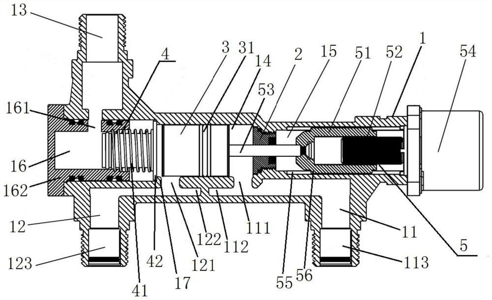
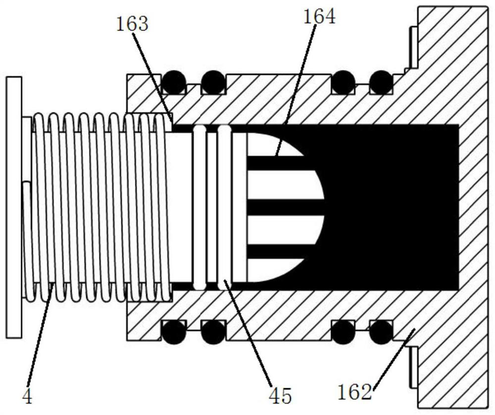
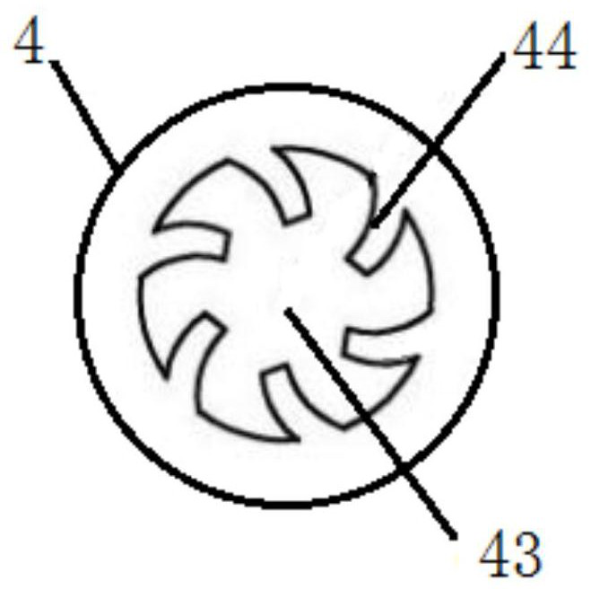
The invention relates to a constant-temperature water valve. A valve body is provided with a mixing passageway, a water outlet passageway and a main passageway communicating with a cold water passageway and a hot water passageway. A water outlet end opening of the cold water passageway and a water outlet end opening of the hot water passageway are arranged at the front end and the rear end of themain passageway correspondingly. A valve element provided with a first hollow channel is arranged in the main passageway. The mixing passageway provided with a mixing water outlet communicates with the water outlet passageway through a water sealing plug provided with a second hollow channel. The power output end of a drive assembly is connected with the valve element, the valve element is drivento move on the main passageway front and back, and the ratio of the water outlet area of the water outlet end opening of the cold water passageway to the water outlet area of the water outlet end opening of the hot water passageway is adjusted. When the constant-temperature water valve is closed, the valve element is driven by the drive assembly to move forwards, and the water sealing plug is pushed to seal the mixing water outlet. When the constant-temperature water valve is opened, the valve element is driven by the drive assembly to move backwards, and the mixing water outlet is opened. Bymeans of the constant-temperature water valve, through the single drive assembly, the water outlet temperature of the constant-temperature water valve can be adjusted, the constant-temperature water valve can be opened and closed, and temperature adjustment is accurate.

Description

technical field [0001] The invention relates to the technical field of valves, in particular to a thermostatic water valve. Background technique [0002] Existing temperature control valves are mainly mechanical temperature control valves and electromagnetic thermostatic valves. Mechanical temperature control valves sense water temperature through heat-sensitive elements (i.e., temperature-memory metal materials). The shape and size of the metal change, and the cold and hot water outlets are adjusted to obtain a constant temperature. The temperature of the mixed water, but it is easily affected by the environment. There are impurities or scale in the water quality, which will adhere to the surface of the memory metal in a short period of time, making the adjusted temperature of the mixed water inaccurate, or even not working; the electromagnetic thermostatic valve adjusts cold and hot through the electromagnetic valve. The proportion of water flow is large, so as to obtain m...

Claims


Application Information

Patent Timeline
Patent Type & Authority Patents(China)
IPC IPC(8): F16K11/07F16K27/04F16K31/04F16K31/50F16K37/00F16K47/08
CPCF16K11/0712F16K27/041F16K31/047F16K31/50F16K37/0091F16K47/08
Inventor 麥克鋒
Owner 鹤山市凯信智造实业有限公司
Why Eureka
Try Eureka