
An offshore lifting platform system

A lifting platform and platform technology, applied in construction, artificial island, infrastructure engineering, etc., can solve problems such as faults, excessive wear, and low durability of offshore lifting platform systems

Inactive Publication Date: 2019-01-18
JINHAI HEAVY IND ZHOUSHAN DESIGN RES INST +1
View PDF5 Cites 0 Cited by
  • Summary
  • Abstract
  • Description
  • Claims
  • Application Information

AI Technical Summary

Problems solved by technology

[0004] In the prior art, the offshore lifting platform system needs to perform on-demand lifting operations during the application process. The lifting platform can also perform vertical position lifting and conversion along the legs on the basis of the support of the legs. In this process, due to In the matching structure of the pile leg and the lifting platform, it is necessary to maintain the dimensional accuracy of the combined structure, and at the same time, it is necessary to protect a certain gap during the lifting process to ensure the smooth progress of the relative movement. Small, in the state of local bending deformation, relative friction and offset limit state will occur between the structures, which will affect the durability of the offshore lifting platform system, and in the long-term use state, it is easy to cause damage and excessive wear of parts , causing the failure to occur
[0005] In the above prior art, the defects such as low durability and high failure rate of the offshore lifting platform system are technical problems that need to be solved by those skilled in the art

Method used


Image

  • An offshore lifting platform system
  • An offshore lifting platform system

Examples


Embodiment Construction

[0016] The core of the present invention is to provide an offshore lifting platform system, through the application of the present invention, the durability of the offshore lifting platform system will be significantly improved, and the failure rate will be reduced at the same time.

[0017] The following will clearly and completely describe the technical solutions in the embodiments of the present invention with reference to the accompanying drawings in the embodiments of the present invention. Obviously, the described embodiments are only some, not all, embodiments of the present invention. Based on the embodiments of the present invention, all other embodiments obtained by persons of ordinary skill in the art without making creative efforts belong to the protection scope of the present invention.

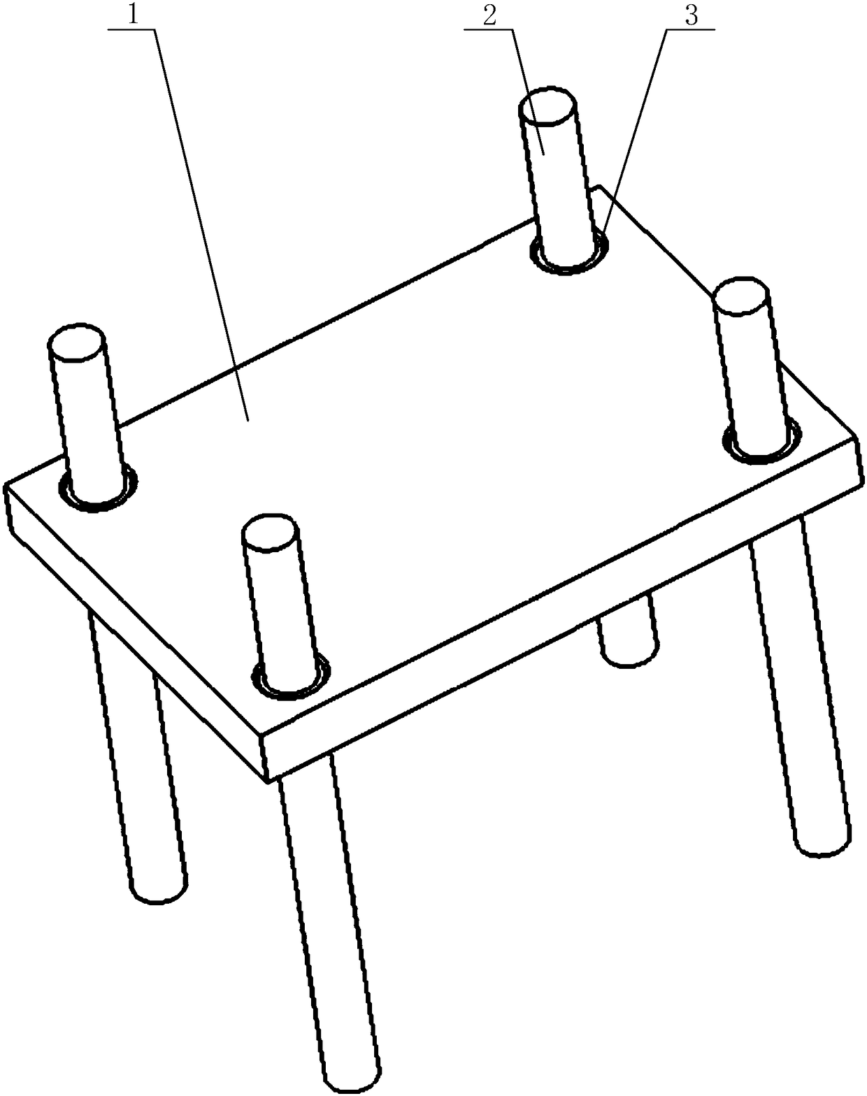
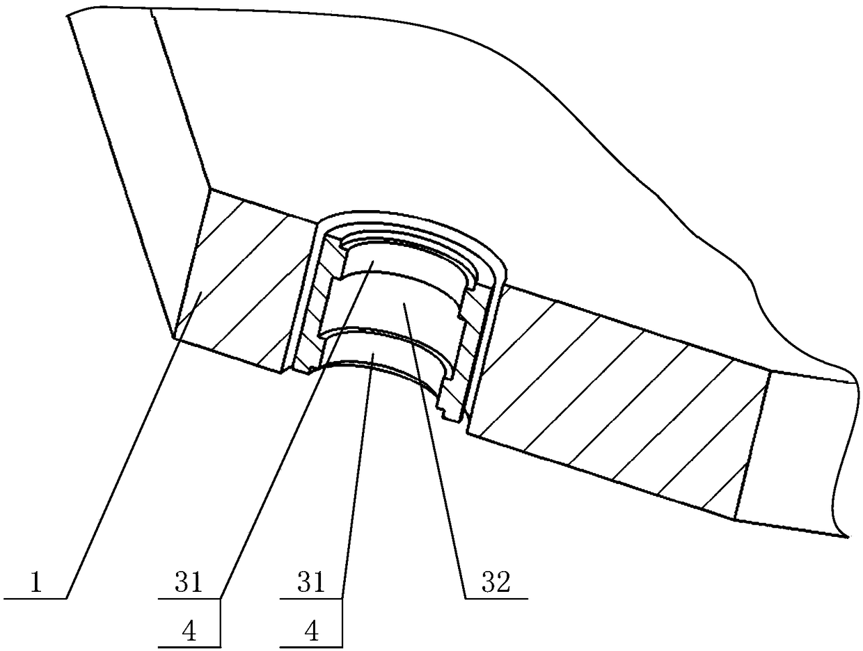
[0018] Please refer to figure 1 and figure 2 , figure 1 An overall schematic diagram of the structure of the application; figure 2 It is a partial sectional view of the stru...


PUM


Abstract

The invention relates to the technical field of ocean operation, in particular to an offshore lifting platform system. The offshore lifting platform system comprises a platform and pile legs used for supporting the platform. The offshore lifting platform system further comprises trunks mounted on the platform. Each trunk comprises a limiting hole segment used for limiting the corresponding pile leg in the radial direction and an allowing hole segment used for allowing deflection deformation of the corresponding pile leg. Each limiting hole segment is coaxial with the corresponding allowing hole segment, each limiting hole segment is arranged at the longitudinal end of the corresponding trunk, each allowing hole segment is arranged in the longitudinal interior of the corresponding trunk, and the outer diameter of each allowing hole segment is larger than the inner diameter of the corresponding limiting hole segment. By means of the above structural arrangement, the limiting hole segments limit the radial positions of the pile legs, meanwhile, the allowing hole segments allow partial deflection deformation, generated by stress, of the pile legs, partial deformation structures and the trunks are prevented from generating abutting extrusion, and therefore the durability of the offshore lifting platform system is improved, and meanwhile the fault rate is decreased.

Description

technical field [0001] The invention relates to the technical field of marine operations, in particular to an offshore lifting platform system. Background technique [0002] With the continuous development of ocean development, various devices are popularized and used. In the process of ocean development, it is usually necessary to apply an offshore lifting platform system. [0003] At present, the requirements for the durability and the reduction of failure rate in the application process of the offshore lifting platform system are getting higher and higher. Therefore, improving the durability and reducing the failure rate have become the design goals of the offshore lifting platform system. [0004] In the prior art, the offshore lifting platform system needs to perform on-demand lifting operations during the application process. The lifting platform can also perform vertical position lifting and conversion along the legs on the basis of the support of the legs. In this pr...

Claims


Application Information

Patent Timeline
Patent Type & Authority Patents(China)
IPC IPC(8): E02B17/08
CPCE02B17/08
Inventor 林伟黄佛生王华余彪伍小瑜戴康利
Owner JINHAI HEAVY IND ZHOUSHAN DESIGN RES INST
Learn More