Eureka AIR delivers breakthrough ideas for toughest innovation challenges, trusted by R&D personnel around the world.

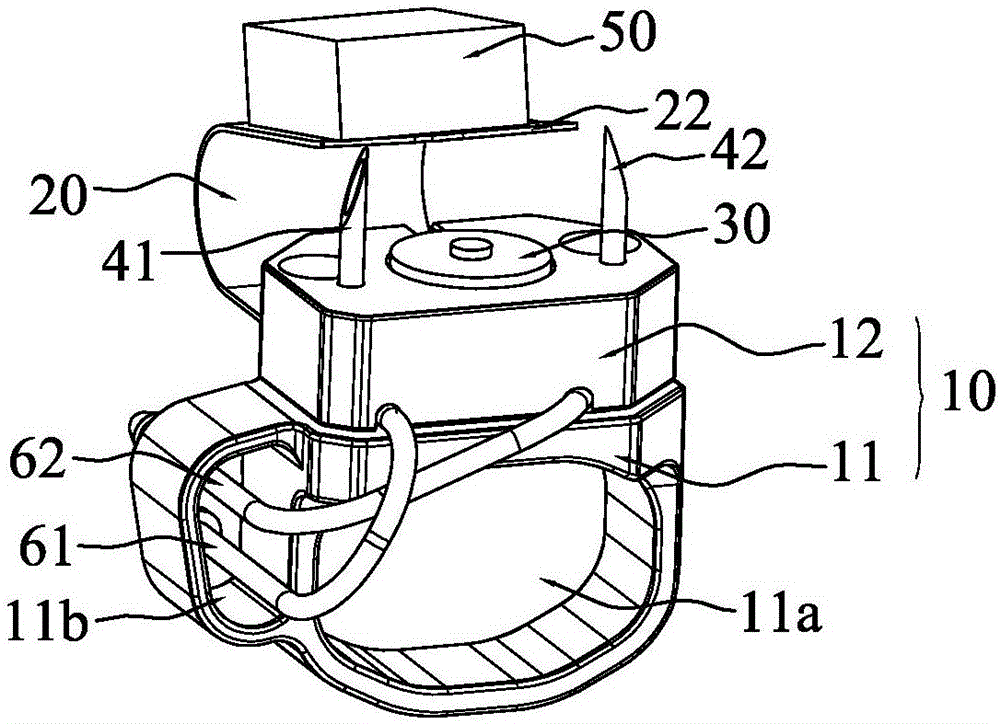
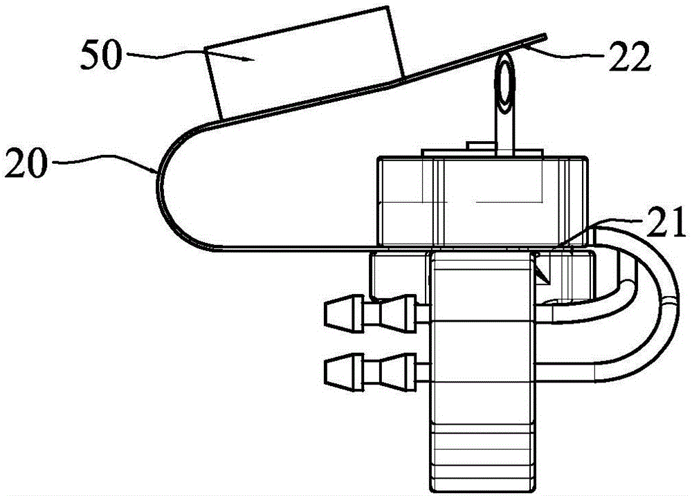
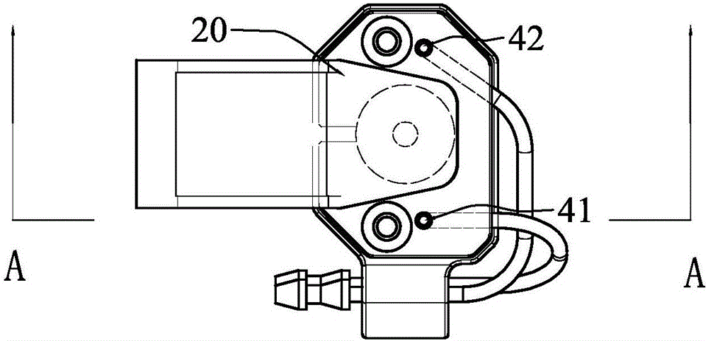
Injection end structure of a syringe and the syringe

A technology for syringes and injection ends, applied in the field of syringes, which can solve problems such as inconvenient injection operations, increased workload of injection personnel, and large volume, and achieve the effect of reducing work intensity

Active Publication Date: 2017-12-29
SHENZHEN ZPWTECHNOLOGY CO LTD
View PDF9 Cites 0 Cited by
  • Summary
  • Abstract
  • Description
  • Claims
  • Application Information

AI Technical Summary

Problems solved by technology

[0002] At present, poultry in large-scale breeding plants need to be vaccinated. Due to the large number of poultry to be injected, syringes are generally required to meet the requirements of continuous injection. Traditional poultry syringes are hand-held, and the piston rod of the syringe A medicine storage bottle loaded with medicine liquid is directly fixed nearby, such as a Chinese utility model patent with a patent number of 02212682.1 and a name called a multifunctional veterinary continuous syringe. The structure of this type of syringe is relatively simple, but the problem is that the injection personnel need to hold the syringe for a long time, which greatly increases the workload of the injection personnel and seriously affects the injection efficiency
[0003] For the above technical problems, the Chinese utility model patent No. 201610212564.0, titled a split-type hand-held automatic injector, proposes a technical solution that can solve the problem. It places the mobile power supply and the large-dose vaccine bottle on The waist is connected with the injection end of the syringe by a pipeline. Although the weight of the hand-held part is reduced by this split design, the injection end of the syringe in this way still adopts the structure of a hand-held injection gun, which is bulky And it is not convenient for injection operation, and the injection efficiency is still not ideal

Method used


Image

  • Injection end structure of a syringe and the syringe
  • Injection end structure of a syringe and the syringe
  • Injection end structure of a syringe and the syringe

Examples


Embodiment Construction

[0023] The idea, specific structure and technical effects of the present invention will be clearly and completely described below in conjunction with the embodiments and accompanying drawings, so as to fully understand the purpose, features and effects of the present invention. Apparently, the described embodiments are only some of the embodiments of the present invention, rather than all of them. Based on the embodiments of the present invention, other embodiments obtained by those skilled in the art without creative efforts belong to The protection scope of the present invention. In addition, all the connection / connection relationships involved in the patent do not simply refer to the direct connection of components, but mean that a better connection structure can be formed by adding or reducing connection accessories according to specific implementation conditions. The various technical features in the present invention can be combined interactively on the premise of not co...


PUM


Abstract

The invention discloses an injection end structure of an injector and the injector and belongs to the technical field of injectors. The injection end structure of the injector comprises a fixing unit, an elastic unit, a switch unit and at least one needle, wherein the a finger ring hole allowing penetration of a finger is formed in the fixing unit, and the switch unit and the at least one needle are fixed on the fixing unit; the elastic unit comprises a fastening end fixedly connected with the fixing unit as well as a moving end capable of reciprocating under the action of external force and own elasticity to trigger the switch unit. The injector comprises the injection end structure and a liquid supply assembly. The injection end structure of the injector meets the requirement of ergonomics and is quite small in size, liquid medicine can be injected timely through the cooperation of the elastic unit and the switch unit, the injection efficiency is high, and injection is convenient.

Description

technical field [0001] The invention relates to a syringe, in particular to an injection end structure of the syringe and the syringe. Background technique [0002] At present, poultry in large-scale breeding plants need to be vaccinated. Due to the large number of poultry to be injected, syringes are generally required to meet the requirements of continuous injection. Traditional poultry syringes are hand-held, and the piston rod of the syringe A medicine storage bottle loaded with medicine liquid is directly fixed nearby, such as a Chinese utility model patent with a patent number of 02212682.1 and a name called a multifunctional veterinary continuous syringe. Cartridge, this type of syringe has a relatively simple structure, but the problem is that the injection personnel need to hold the syringe for a long time, which greatly increases the workload of the injection personnel and seriously affects the injection efficiency. [0003] For the above technical problems, the C...

Claims


Application Information

Patent Timeline
Patent Type & Authority Patents(China)
IPC IPC(8): A61D7/00
CPCA61D7/00
Inventor 张岩
Owner SHENZHEN ZPWTECHNOLOGY CO LTD
Why Eureka
Eureka Blog
Learn More