Eureka AIR delivers breakthrough ideas for toughest innovation challenges, trusted by R&D personnel around the world.

Termite detection device and detection method thereof

A detection device and detection method technology, which are applied to the device, application, animal husbandry, etc. of catching or killing insects, can solve the problems of low false alarm rate, high false alarm rate, environmental pollution of termite control device, etc., and achieve false alarm The effect of low rate and long service life

Active Publication Date: 2016-12-21
ZHEJIANG DEKAN ENVIRONMENT TECH CO LTD
View PDF5 Cites 4 Cited by
  • Summary
  • Abstract
  • Description
  • Claims
  • Application Information

AI Technical Summary

Problems solved by technology

[0005] In view of the problems existing in the above-mentioned prior art, the present invention proposes a termite detection device and its detection method, which uses air in the sealed hole in the bait bar to detect whether the air pressure in the hole can reach the preset value after inflating for a period of time. Detect whether the sealing hole is bitten by termites, so as to detect whether there are termites. It is non-medicine control and will not pollute the environment. It has a wide range of applications and a low false alarm rate. It solves the environmental pollution existing in the existing termite control devices. The problem of high false positive rate

Method used


Image

  • Termite detection device and detection method thereof
  • Termite detection device and detection method thereof
  • Termite detection device and detection method thereof

Examples


Embodiment 1

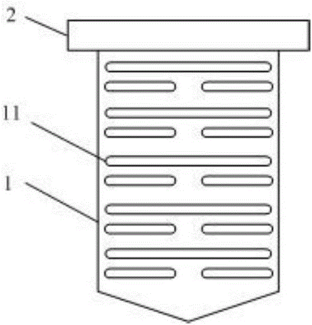
[0045] combine Figure 1-Figure 2 , this embodiment describes in detail the termite detection device of the present invention, as figure 1 Shown is a schematic diagram of its external structure, which includes: a casing 1 and a top cover 2, the top cover 2 is set on the top of the casing 1, and the casing 1 is provided with an opening 11 that allows termites to enter. Such as figure 2 Shown as its cross-sectional view, the housing 1 is provided with a bait strip 3 that termites like to eat, and the bait strip 3 is provided with a sealed deep hole 31 . The termite detecting device of the present embodiment also includes: gas cylinder 4, controller 6, air pressure sensor 7, gas cylinder 4 is connected with deep hole 31 through switch 5, when switch 5 is opened, gas cylinder 4 is inflated in deep hole 31; Air pressure sensor 7 is arranged on the inner side of deep hole 31, is used for sensing the air pressure in deep hole 31; Check whether the air pressure reaches the preset ...

Embodiment 2

[0056] This embodiment is on the basis of Embodiment 1, the controller 6 is connected with the switch 5, the switch 5 is no longer manually opened or closed, and the controller 6 can be used to transmit a trigger signal to control the opening or closing of the switch 5, reducing the Staff participation saves workload. Specifically: the controller 6 transmits the first trigger signal, the control switch 5 is opened, and after a delay of the second preset time, the controller 6 transmits the second trigger signal, the control switch 5 is closed, and the second preset time is greater than or equal to the first preset time time.

[0057] In different embodiments, the first trigger signal can be randomly transmitted, and when detection is required, the manual control controller 6 transmits the first trigger signal for the switch 5; it can also be a timing transmission, which is set by a program in the controller 6, and the timing A first trigger signal is transmitted for switch 5 ...

Embodiment 3

[0059] combine Figure 4 , the present embodiment describes in detail the termite detection method of the present invention, which is a detection method implemented by the termite detection system of Embodiment 1, which includes the following steps:

[0060] S11: When detection is required, turn on the switch manually, and the gas cylinder will inflate the deep hole in the bait bar;

[0061] S12: The controller judges whether the air pressure sensed by the air pressure sensor inside the deep hole reaches the preset air pressure value after the first preset time after the switch is turned on. If it reaches the preset air pressure value, it means that the deep hole has not been bitten through by termites. All the air pressure sensors in the deep hole quilt sensed that the air pressure reaches the preset air pressure value, indicating that there are no termites; if the air pressure sensor does not reach the preset air pressure value, it means that the deep hole is bitten through ...


PUM


Abstract

The invention discloses a termite detection device and a detection method thereof. The device comprises a shell with openings allowing termites to enter and bait bars arranged in the shell, each bait bar is provided with a sealed deep hole, and each deep hole is internally provided with an air pressure sensor; the device further comprises air bottles and a controller; the air bottles are communicated with the deep holes through a switch, and when the switch is switched on, the air bottles inflate the deep holes; the controller is connected with the air pressure sensors and used for judging whether air pressure sensed by the air pressure sensors reaches a preset air pressure value or not after a first preset time after the switch is switched on, if yes, it is shown that the deep holes are not bitten through by the termites, and if not, it is shown that the deep holes are bitten through by the termites. The method comprises the steps that the switch is switched on, and the deep holes are inflated; after the first preset time, whether the air pressure reaches the preset air pressure value or not is judged, and therefore whether the deep holes are bitten through or not is judged. According to the termite detection device and the detection method thereof, no drug prevention is needed, the environment cannot be polluted, the application range is wide, and the false alarm rate is low.

Description

technical field [0001] The invention relates to the field of termite control, in particular to a termite detection device and detection method. Background technique [0002] Termites are one of the five major pests in the world, especially in tropical and subtropical regions. Termites can eat all plants, and the formic acid secreted in their bodies can also corrode steel bars and denature concrete. Termites have brought a lot of damage to people's daily life, including damage to buildings, dams, crops, books, underground cables, etc. The damage is hidden, such as the damage of termites to buildings, especially to brick and wood structures 1. The destruction of wooden structure buildings is often concealed inside the structure. The surface of the damaged object appears to be intact, but the inside is riddled with holes, often causing the house to collapse, resulting in property loss and casualties. [0003] For a long time, the method of preventing and controlling termites ...

Claims


Application Information

Patent Timeline
IPC IPC(8): A01M1/02
CPCA01M1/026
Inventor 沈俊峰汪亦中钱掌清顾征毅金磊费一鸣
Owner ZHEJIANG DEKAN ENVIRONMENT TECH CO LTD
Why Eureka
Eureka Blog
Learn More