
Landscape decoration lamp system and automatic address coding method thereof

An address coding and decorative lighting technology, applied in the field of landscape decorative lighting system and automatic address coding, can solve the problems of increasing system cost, display module cannot work normally, strict system cost, etc., and achieves the effect of overcoming complicated calculation and troublesome operation.

Active Publication Date: 2016-12-14
SHENZHEN SUNMOON MICROELECTRONICS
View PDF6 Cites 15 Cited by
  • Summary
  • Abstract
  • Description
  • Claims
  • Application Information

AI Technical Summary

Problems solved by technology

[0002] At present, in the landscape decorative lighting system, the traditional serial landscape lighting system will cause the subsequent display modules to fail to work normally due to the failure of one or more serial display modules; and the parallel landscape decorative lighting system can effectively solve the traditional problem. The problem that the series series landscape light system is easy to fail to work when the received display data is transmitted step by step in series, and has been widely used; however, although the parallel landscape light system has indeed improved in terms of performance and reliability, but At the same time, it also increases the system cost to a certain extent; and in most engineering cases, the control of system cost is relatively strict, which often makes users fall into a dilemma when choosing what kind of landscape decorative lighting system

Method used


Image

  • Landscape decoration lamp system and automatic address coding method thereof
  • Landscape decoration lamp system and automatic address coding method thereof
  • Landscape decoration lamp system and automatic address coding method thereof

Examples


Embodiment Construction

[0025] The preferred embodiments of the present invention will be further described in detail below in conjunction with the accompanying drawings.

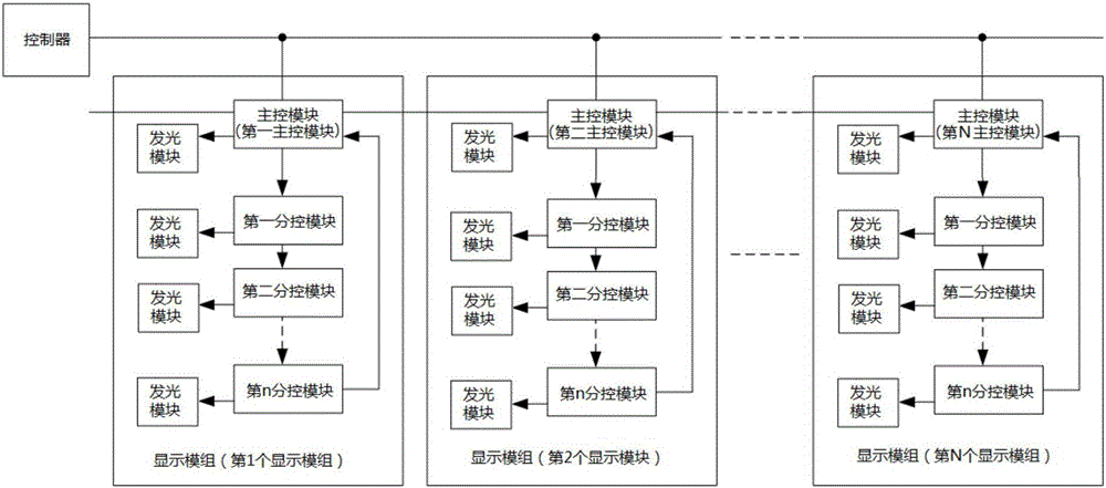
[0026] Such as figure 1 As shown, this example provides a landscape decorative lighting system, including: a controller and at least two display modules, the input end of each display module is connected to the output end of the controller, specifically, each The display data input terminals of one of the display modules are connected to the display data output terminals of the controller; each of the display modules includes a main control module and one or more sub-control modules, the same display module The sub-control modules in the display module are sequentially connected in series at the rear stage of the main control module of the display module; preferably, each of the display modules in this example includes more than two sub-control modules, and the two or more sub-control modules include The first sub-control module ...


PUM


Abstract

The invention provides a landscape decoration lamp system and an automatic address coding method thereof. The landscape decoration lamp system comprises a controller and at least two display modules, the input end of each display module is connected to the output end of the controller, each display module comprises a main control module and one or more sub-control modules, and the sub-control modules in the same display module are serially connected to the later stage of the main control module of the display module in sequence; the controller is used for sending display data and an address coding instruction; each display module carries out automatic address coding operation according to the received address coding instruction, and intercepts corresponding display data for displaying according to self address coding data after receiving the display data. The landscape decoration lamp system overcomes the defects of a parallel landscape decoration lamp system and a series landscape decoration lamp system on cost and performance respectively, and can avoid complex calculation caused by using the controller to carry out address coding on each display module in the prior art.

Description

technical field [0001] The invention relates to a decorative lamp, in particular to a landscape decorative lamp system and an automatic address coding method applied to the landscape decorative lamp system. Background technique [0002] At present, in the landscape decorative lighting system, the traditional serial landscape lighting system will cause the subsequent display modules to fail to work normally due to the failure of one or more serial display modules; and the parallel landscape decorative lighting system can effectively solve the traditional problem. The problem that the series series landscape light system is easy to fail to work when the received display data is transmitted step by step in series, and has been widely used; however, although the parallel landscape light system has indeed improved in terms of performance and reliability, but At the same time, it also increases the system cost to a certain extent; and in most engineering cases, the control of syst...

Claims


Application Information

Patent Timeline
IPC IPC(8): H05B37/02G09G3/20G09G3/22
CPCG09G3/2088G09G3/22H05B47/10
Inventor 李照华符传汇陈克勇方曙
Owner SHENZHEN SUNMOON MICROELECTRONICS
Learn More