
Single-frequency laser interferometer non-linear error compensation device

A technology of nonlinear error and compensation device, which is applied in the direction of using optical devices, measuring devices, instruments, etc., can solve problems such as incompleteness and no public reports, and achieve the effect of compensating nonlinear errors

Active Publication Date: 2016-12-14
HEFEI UNIV OF TECH
View PDF6 Cites 34 Cited by
  • Summary
  • Abstract
  • Description
  • Claims
  • Application Information

AI Technical Summary

Problems solved by technology

Some existing analyzes on the nonlinear error of polarization beam splitters regard all polarization beam splitters in the optical path as the same; some of them only consider the influence of polarization beam splitters in the detection part on nonlinearity when compensating for nonlinear errors of optical components. Neglecting the nonlinearity caused by the interference part of the polarization beamsplitter prism, these methods are not comprehensive; so far, there is no analysis from the influence mechanism of the polarization beamsplitter prism on the triple difference, that is, DC bias, unequal amplitude and phase non-orthogonal The nature of the source of the nonlinearity, and there is no published report on the device to eliminate the phase non-orthogonal from the layout of the optical structure

Method used


Image

  • Single-frequency laser interferometer non-linear error compensation device
  • Single-frequency laser interferometer non-linear error compensation device
  • Single-frequency laser interferometer non-linear error compensation device

Examples


Embodiment Construction

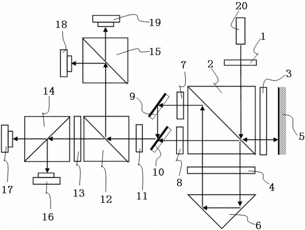
[0036] see figure 1 , the structural form of the nonlinear error compensation device of the single-frequency laser interferometer in this embodiment is:

[0037]The light beam emitted by the laser 20 exits the first linear polarizer 1 as a beam of 45° linearly polarized light A11, and the linearly polarized light A11 is split by the first polarizing beam splitter 2 into the transmitted light A21 of the P component and the reflected light A22 of the S component. The angle between the direction of the transmission axis of the first linear polarizer 1 and the horizontal axis of the plane on which it is located is 45°, to ensure that what is incident on the first polarizing beam splitter 2 is 45° linearly polarized light, because the polarizing beam splitting prism is only for the 45° line Polarized light is evenly split, see Figure 6 .

[0038] The transmitted light A21 is converted into circularly polarized light by the first quarter-wave plate 4 as the reference light and th...


PUM


Abstract

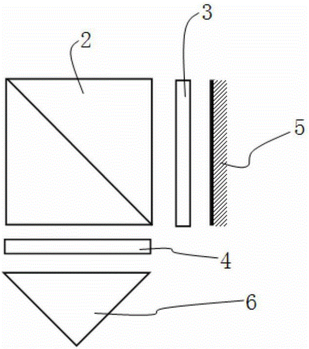
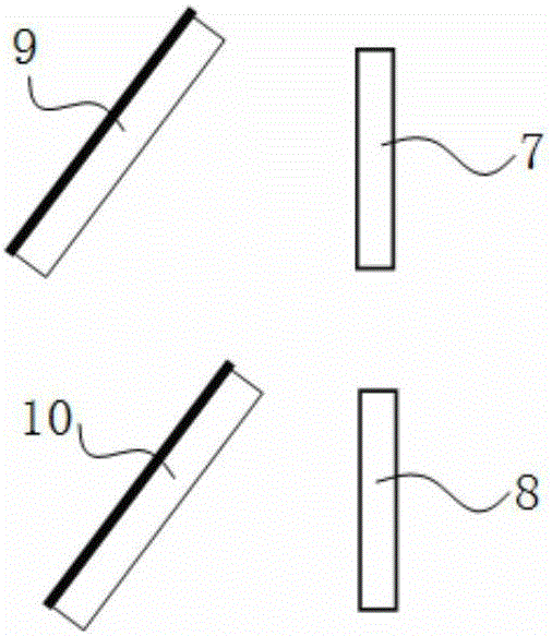
The present invention discloses a single-frequency laser interferometer non-linear error compensation device. The single-frequency laser interferometer non-linear error compensation device is characterized in that after a light beam emitted by a laser is split by a polarization splitting prism, the transmitted light is projected to a rectangular prism and is returned to the polarization splitting prism to form the reference light S; the reflected light is projected to a plane mirror and is returned to the polarization splitting prism to form the measurement light P; a linear polaroid along an S direction is placed in a reference light path, and a linear polaroid along a P direction is arranged in a measurement light path, thereby realizing the nonorthogonal error compensation; the semi-transparent and semi-reflective mirrors are arranged in the emergent light paths of the linear polaroids, so that the reference light and the measurement light are combined and then are split by a depolarization splitting prism evenly, the transmitted light generates the interference signals I1 and I2 via a quarter-wave plate and the polarization splitting prism, the reflected light generates the interference signals I3 and I4 via the polarization splitting prism, and the mutual phase difference of the signals I1, I2, I3 and I4 is 90 degrees. According to the present invention, a non-linear error of the single-frequency laser interferometer is compensated effectively.

Description

technical field [0001] The invention belongs to the technical fields of optical measurement, high-precision testing and precision measurement, and particularly relates to a nonlinear error compensation device for a single-frequency laser interferometer. Background technique [0002] With the rapid development of nanotechnology and integrated chip fields and the continuous improvement of the precision of modern manufacturing industry, higher requirements are put forward for the measurement resolution of small displacement. Among many methods capable of measuring small displacements, laser interferometry technology is widely used in precision and ultra-precision measurement due to its high resolution and non-contact measurement. In particular, laser interferometry technology is traceable. When it is traceable to the definition of meters, other measurement methods still need laser interferometers for calibration and calibration. At present, the commonly used homodyne laser int...

Claims


Application Information

Patent Timeline
IPC IPC(8): G01B9/02
CPCG01B9/02056
Inventor 王超群黄强先伍婷婷张连生
Owner HEFEI UNIV OF TECH
Learn More