
Plunger cylinder, pumping system swing valve mechanism and concrete pumping equipment

A plunger cylinder and plunger rod technology, which is applied in the field of concrete pumping equipment, can solve the problems of affecting the service life of the plunger cylinder, easy oil leakage of the plunger type cylinder, and reducing the working performance of the plunger cylinder, and achieves a simple and ingenious structure Effect

Inactive Publication Date: 2016-12-14
BEIQI FOTON MOTOR CO LTD
View PDF7 Cites 4 Cited by
  • Summary
  • Abstract
  • Description
  • Claims
  • Application Information

AI Technical Summary

Problems solved by technology

When the plunger rod of the plunger cylinder is retracted under force, it will have a large impact on the bottom of the plunger cylinder, which will affect the service life of the plunger cylinder and reduce the working performance of the plunger cylinder.
[0004] The structure of the traditional plunger cylinder is complicated, and there are many assembly joints between the parts, which leads to the oil leakage of the plunger cylinder and its heavy weight
In addition, in order to meet the needs of the work, the processing technology and quality requirements of the plunger cylinder are also very high, resulting in high manufacturing costs

Method used


Image

  • Plunger cylinder, pumping system swing valve mechanism and concrete pumping equipment

Examples


Embodiment Construction

[0035] Specific embodiments of the present disclosure will be described in detail below in conjunction with the accompanying drawings. It should be understood that the specific implementations described here are only used to illustrate and explain the present disclosure, not to limit the present disclosure.

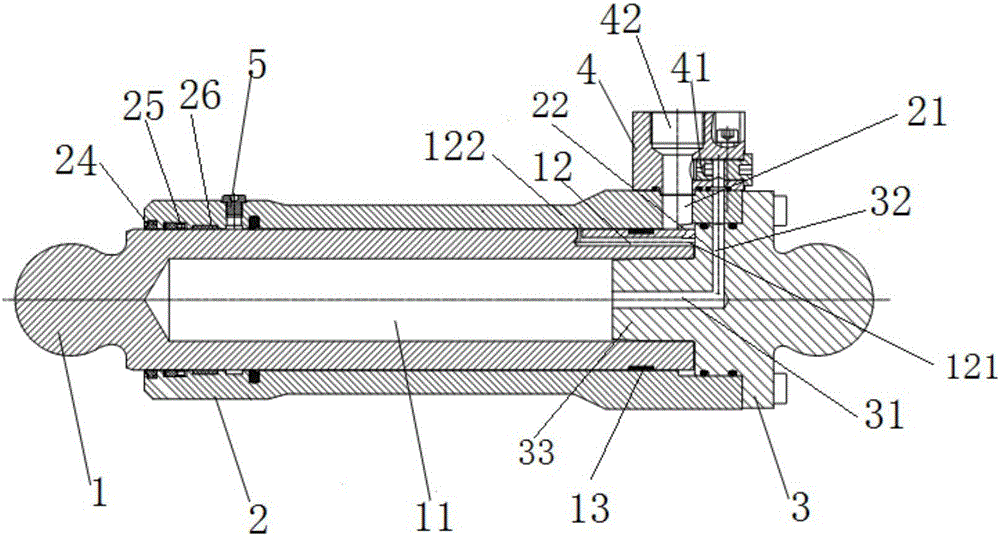
[0036] Such as figure 1 As shown, according to one aspect of the present disclosure, a plunger cylinder is provided, including a plunger rod 1, a cylinder barrel 2 and a cylinder bottom 3, the cylinder barrel 2 has a first end and a second end, and the plunger rod 1 is connected from the cylinder barrel The first end of 2 is movably installed in the inner cavity of the cylinder 2 and is close to the inner wall of the cylinder 2, the cylinder bottom 3 is located at the second end of the cylinder 2, and the plunger cylinder has an oil port 42 and communicates with the oil The port 42 is connected to the first oil passage 21 of the inner cavity, so that the oil inlet and oi...


PUM


Abstract

The invention relates to a plunger cylinder, a pumping system swing valve mechanism and concrete pumping equipment. The plunger cylinder comprises a plunger rod, a cylinder barrel and a cylinder bottom, wherein the cylinder barrel is provided with a first end and a second end; the plunger rod is movably sleeved in an inner cavity of the cylinder barrel from the first end of the cylinder barrel and is tightly attached to the side wall of the cylinder barrel; the cylinder bottom is located at the second end of the cylinder barrel; the plunger cylinder is provided with an oil opening and a first oil channel which enables the oil opening and the inner cavity to communicate; and the plunger cylinder is further provided with a throttling oil channel, and the throttling oil channel and the first oil channel are connected between the oil opening and the inner cavity in parallel. The plunger rod can block the first oil channel while retracting under stress so that hydraulic oil of the inner cavity can flow towards the oil opening after being throttled mainly by the throttling oil channel, and then buffering of the plunger rod is achieved through throttling on the hydraulic oil; and the hydraulic oil at the oil opening is supplied to the inner cavity mainly through the first oil channel in the outward extension process of the plunger rod, and accordingly normal operation of the plunger rod is achieved.

Description

technical field [0001] The present disclosure relates to the field of engineering machinery, and in particular, to a plunger cylinder, a pumping system swing valve mechanism using the plunger cylinder, and concrete pumping equipment including the pumping system swing valve mechanism. Background technique [0002] The plunger cylinder has a wide range of applications, such as being applied to the hopper of a pump truck, so that the S pendulum valve on the hopper swings intermittently to distribute the concrete into the corresponding delivery pipe. [0003] Due to work requirements, the plunger cylinder needs to complete short-distance operation under high pressure and high speed, and is usually a single-acting cylinder, that is, it needs to be retracted under force. And when the plunger rod of the plunger oil cylinder is stressed and withdraws the cylinder barrel, the cylinder bottom of the plunger oil cylinder is greatly impacted, which affects the service life of the plunge...

Claims


Application Information

Patent Timeline
IPC IPC(8): F15B15/22F15B15/14
CPCF15B15/22F15B15/1414F15B15/1428
Inventor 张博周龙
Owner BEIQI FOTON MOTOR CO LTD
Learn More