
Laser processing system and laser focusing method

A laser processing and laser technology, which is applied in the field of laser processing system and laser focusing, can solve the problems of poor processing effect, surface image difference, affecting processing yield, etc.

Active Publication Date: 2018-04-27
深圳市大族微加工软件技术有限公司
View PDF5 Cites 0 Cited by
  • Summary
  • Abstract
  • Description
  • Claims
  • Application Information

AI Technical Summary

Problems solved by technology

However, due to differences in the production process of sapphire wafers, there will be differences in the surface images obtained by the imaging system, such as different grinding processes between different batches of products, differences in coating uniformity, and differences in wafer thickness between batches. etc. These factors will affect the laser processing system to find errors in the position of the sapphire surface during mass production, which will cause differences between the depth of laser processing and the preset value, resulting in poor processing results, or the specific position of the surface cannot be found, resulting in The laser processing system cannot enter the next process and generates an alarm. All these factors eventually lead to a decrease in the stability of the laser processing system and affect the overall processing yield

Method used


Image

  • Laser processing system and laser focusing method
  • Laser processing system and laser focusing method
  • Laser processing system and laser focusing method

Examples


Embodiment Construction

[0040] In order to facilitate the understanding of the present invention, the present invention will be described more fully below with reference to the associated drawings. Preferred embodiments of the invention are shown in the accompanying drawings. However, the present invention can be embodied in many different forms and is not limited to the embodiments described herein. On the contrary, the purpose of providing these embodiments is to make the disclosure of the present invention more thorough and comprehensive.

[0041] It should be noted that when an element is referred to as being “fixed” to another element, it can be directly on the other element or there can also be an intervening element. When an element is referred to as being "connected to" another element, it can be directly connected to the other element or intervening elements may also be present. The terms "vertical," "horizontal," "left," "right," and similar expressions are used herein for purposes of ill...


PUM

PropertyMeasurementUnit
thicknessaaaaaaaaaa

Abstract

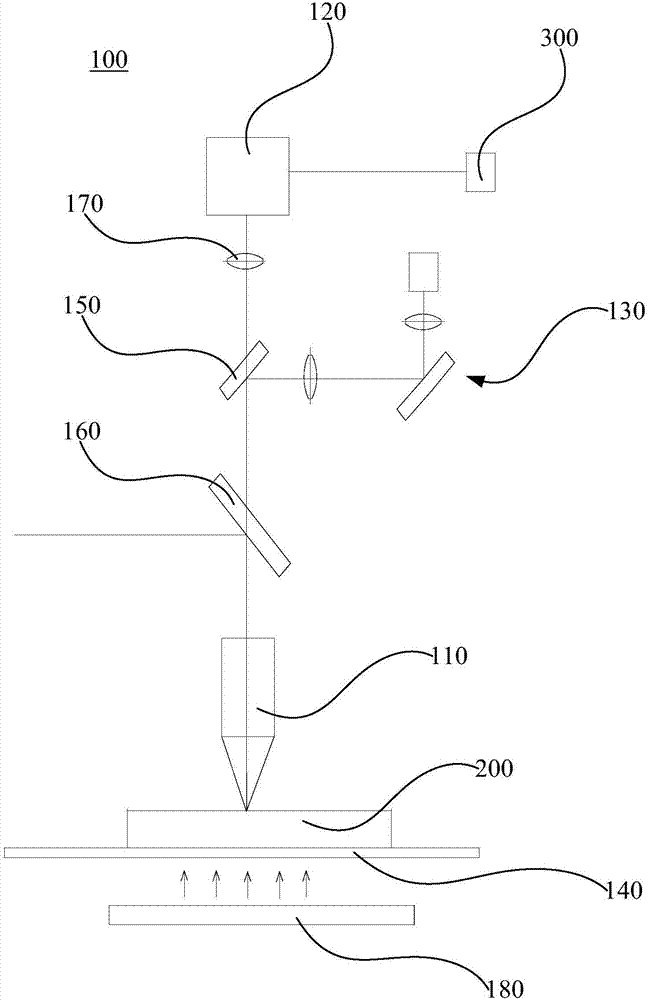
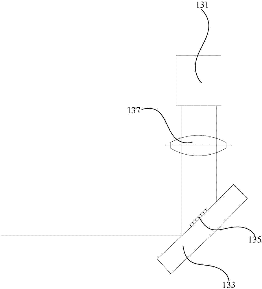
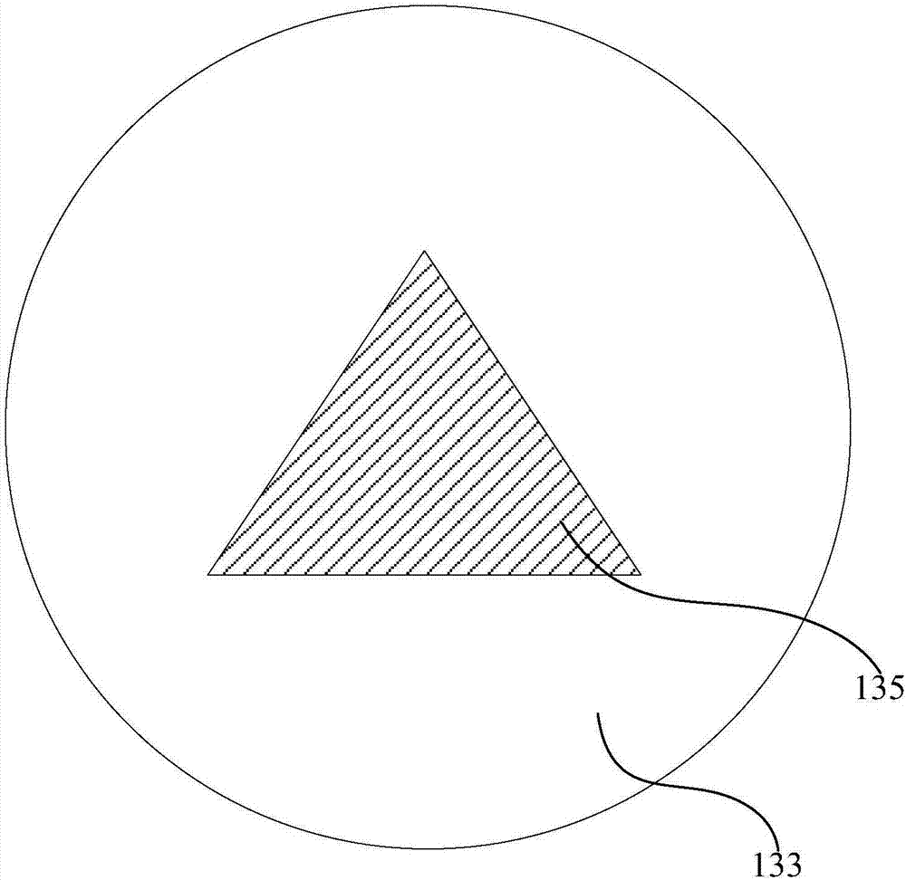
The invention relates to a laser processing system and a laser focusing method. The laser processing system comprises a laser generator, a focusing objective lens, a CCD camera and a marker mechanism; laser generated by the laser generator is converged through the focusing objective lens, and is imaged through the focusing objective lens; the focusing objective lens is an imaging objective lens of the CCD camera; a focus of the focusing objective lens is superposed with an imaging focal plane of the CCD camera; the marker mechanism comprises a first light source, a reflecting mirror and a marker; the marker fits to the reflecting mirror; light emitted by the first light source irradiates the reflecting mirror, passes through the focusing objective lens, and finally forms a virtual image of the marker on the imaging focal plane of the CCD camera. According to the laser processing system and the laser focusing method using same, recognition degree on images is high, errors are small, searching precision for a precise height value, at which the focus drops on the surface of a wafer surface, of the focusing objective lens is relatively high, depth control on laser processing is very good, and integral yield of laser processing can be increased.

Description

technical field [0001] The invention relates to the field of laser processing, in particular to a laser processing system and a laser focusing method. Background technique [0002] In the field of laser micro-precision processing such as LED wafer semiconductors, sapphire is generally used as the substrate material, and the light-emitting area is deposited on the sapphire substrate. The thickness of the light-emitting area is generally only 3-6 μm, and the thickness of sapphire is generally 80-150 μm. . [0003] Currently, lasers are generally used to process LED wafers to separate them into individual small dies. Laser processing is generally incident from the sapphire surface of the wafer to a certain depth, which has strict precision requirements for the depth. For LED wafers with a certain thickness, the depth of laser processing has a direct impact on the quality of processing. [0004] The traditional laser processing method is to first use the imaging system to fin...

Claims


Application Information

Patent Timeline
Patent Type & Authority Patents(China)
IPC IPC(8): B23K26/046B23K26/38B23K26/08
CPCB23K26/046B23K26/08B23K26/38
Inventor 王焱华庄昌辉李福海曾威朱炜尹建刚高云峰
Owner 深圳市大族微加工软件技术有限公司
Learn More