Supercharge Your Innovation With Domain-Expert AI Agents!

Intermediate-energy semi-automatic shielding electron accelerator

An electron accelerator and accelerator technology, applied in the fields of magnetic/electric field shielding, electrical components, metal containers, etc., can solve the problems of long construction period, high investment cost, and high shielding room height, and achieve the effect of reducing height

Inactive Publication Date: 2016-12-07
CGN DASHENG ELECTRON ACCELERATOR TECH
View PDF11 Cites 2 Cited by
  • Summary
  • Abstract
  • Description
  • Claims
  • Application Information

AI Technical Summary

Problems solved by technology

During the operation of the accelerator, the electron beam passes through the electron gun, accelerating tube, vacuum system and scanning extraction system, and finally irradiates on the product. In the process of beam generation and irradiation on the product, beams will inevitably be generated. Flow scattering bombardment produces radiation on the accelerating tube or other metal surfaces, and most of the electron beams are absorbed by the product during the irradiation process, but a small amount of electron beams bombard the equipment, because when the electron beams bombard metal materials, Bremsstrahlung (a type of radiation produced when high-energy charged particles are suddenly decelerated) occurs in metal materials to produce X-rays; therefore, it is necessary to build a shielding room to shield the human body from the radiation. Conventional shielding methods include concrete infrastructure for shielding rooms and accelerators. open shielding, existing structures such as figure 2 As shown, but this shielding method has high investment costs, a long construction period, and the height of the shielding room is very high, and conventional standard factory buildings cannot be built and installed

Method used


Image

  • Intermediate-energy semi-automatic shielding electron accelerator
  • Intermediate-energy semi-automatic shielding electron accelerator

Examples


Embodiment Construction

[0014] The present invention will be further described below in conjunction with the accompanying drawings.

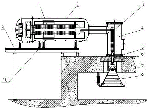
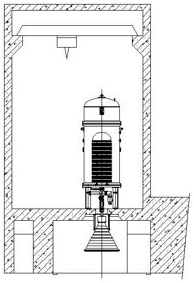
[0015] Such as figure 1 As shown, a medium-energy semi-self-shielded electron accelerator includes a connected power supply steel cylinder 2 and an accelerator steel cylinder 4. An accelerator power supply 1 is installed in the power supply steel cylinder 2, and an accelerator power supply 1 is installed in the accelerator steel cylinder 4. Tube 3, the accelerator steel cylinder 4 is fixed on the shielding installation plate 6, the shielding installation plate 6 is fixed on the shielding wall 7 on the upper part of the shielding room, and the vacuum device 5 and the scanning extraction device 8 are connected below the acceleration tube 3 , and the vacuum device 5 and the scanning extraction device 8 are all arranged in the shielding room, and the power supply steel cylinder 2 and the accelerator steel cylinder 4 are in an L-shaped installation structure, wherein the p...


PUM


Abstract

The invention discloses an intermediate-energy semi-automatic shielding electron accelerator. The intermediate-energy semi-automatic shielding electron accelerator comprises a power supply steel cylinder and an accelerator steel cylinder which are connected, wherein an accelerator power supply is arranged in the power supply steel cylinder, an acceleration pipe is arranged in the accelerator steel cylinder, the accelerator steel cylinder is fixed on a shielding installation plate, the shielding installation plate is fixed on a shielding wall at an upper part of a shielding room, a vacuum device and a scanning leading-out device are connected to a part below the acceleration pipe and are both arranged in the shielding room, the power supply steel cylinder and the accelerator steel cylinder form an L-shaped installation structure, the power supply steel cylinder is in a horizontal state, and the accelerator steel cylinder is in a vertical state. By the power supply steel cylinder and the accelerator steel cylinder in the L-shaped structure, the automatic shielding of the accelerator power supply and the acceleration pipe is achieved, the height of the shielding room can be effectively reduced, and the device compactness is improved.

Description

technical field [0001] The invention relates to a medium-energy semi-self-shielding electron accelerator, which belongs to the technical field of accelerator manufacturing. Background technique [0002] Industrial irradiation electron accelerators have gradually entered my country's irradiation processing market since the 1980s, and have created huge economic benefits in the irradiation processing of heat-shrinkable products and wires and cables. Domestic manufacturers using electron accelerators for irradiation are also increasing. more. During the operation of the accelerator, the electron beam passes through the electron gun, accelerating tube, vacuum system and scanning extraction system, and finally irradiates on the product. In the process of beam generation and irradiation on the product, beams will inevitably be generated. Flow scattering bombardment produces radiation on the accelerating tube or other metal surfaces, and most of the electron beams are absorbed by th...

Claims


Application Information

Patent Timeline
IPC IPC(8): H05H7/00H05K9/00
CPCH05H7/00H05K9/0049
Inventor 朱焕铮倪振天
Owner CGN DASHENG ELECTRON ACCELERATOR TECH
Features
  • R&D
  • Intellectual Property
  • Life Sciences
  • Materials
  • Tech Scout
  • Unparalleled Data Quality
  • Higher Quality Content
  • 60% Fewer Hallucinations
Learn More