
Robot hub brushless DC motor controller and control method thereof

A brushless DC motor and control method technology, applied in the direction of speed/torque control of a single motor, can solve the problems of lack of availability and inability to popularize hub motors, and achieve improved response speed, reduced speed fluctuations, and simplified control algorithms Effect

Active Publication Date: 2016-12-07
王宏涛
View PDF5 Cites 4 Cited by
  • Summary
  • Abstract
  • Description
  • Claims
  • Application Information

AI Technical Summary

Problems solved by technology

According to different control methods and wheel distribution, wheeled robots have various forms such as two-wheel differential, omni-directional wheels, and driving wheels. Although there are various forms, they are all driven by motors to realize the movement of the robot. The core component of the robot powertrain system needs to meet the requirements of the robot controller for speed closed-loop control and position feedback. At present, the hub motor widely used in the field of electric vehicles is installed in the hub of the wheel, and the output torque is directly transmitted to the Wheels, thus abandoning traditional mechanical components such as clutches, reducers, transmission bridges, differentials, etc., reducing the weight of the vehicle and reducing mechanical transmission losses. Considering the obvious advantages of hub motors, in recent years, the field of robots The industry is constantly trying to introduce hub motors into robot drive systems. However, hub motors do not have communication functions, use analog control, and do not have speed closed-loop and position feedback functions. Widely used in robots

Method used


Image

  • Robot hub brushless DC motor controller and control method thereof
  • Robot hub brushless DC motor controller and control method thereof
  • Robot hub brushless DC motor controller and control method thereof

Examples


Embodiment

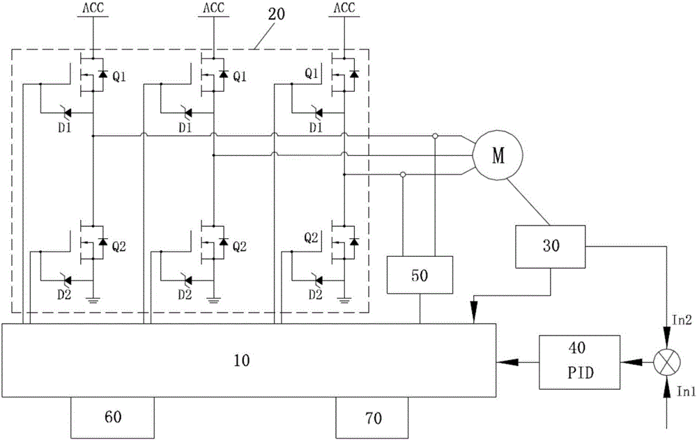
[0075] Such as figure 1 As shown, this embodiment provides a hub motor controller that applies a hub DC brushless motor to a robot hub drive system. The DC brushless motor forming a wheeled robot driver in the present invention is a common hub motor with three phases wire and 5 signal wires, 3 phase wires provide power for the motor, and 5 signal wires are respectively +5V, GND, Ha, Hb, and Hc to provide signals for the motor commutation. The invention does not modify the hub motor and uses it directly The original phase line and signal line are used as input, which can realize speed closed-loop control and position feedback. The specific structure is as follows:

[0076] Including a control circuit 10, a three-phase drive bridge circuit 20 for driving a brushless DC motor M, the signal output terminal of the control circuit 10 is connected to the three-phase drive bridge circuit 20, and also includes a Hall sensor 30, the Hall The acquisition signal input end of the sensor 3...


PUM


Abstract

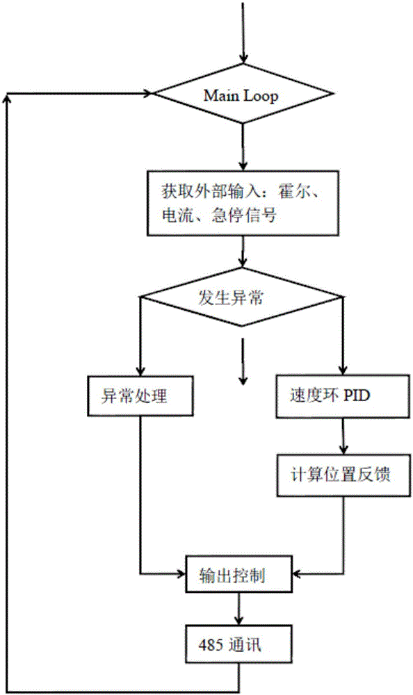
The invention provides a hub motor controller which is used for applying a hub brushless DC motor to a robot hub driving system. The hub motor controller comprises a control circuit and a three-phase driving bridge circuit and also comprises a Hall sensor, wherein the three-phase driving bridge circuit drives a brushless DC motor, a signal output end of the control circuit is in control connection with the three-phase driving bridge circuit, an acquisition signal input end of the Hall sensor is connected with the brushless DC motor, an acquisition signal output end of the Hall sensor is connected with the control circuit, the control circuit measures and calculates a rotor position of the brushless DC motor according to an acquisition result of the Hall sensor, the acquisition signal output end of the Hall sensor is connected to the control circuit through a speed closed-loop regulator, the speed closed-loop regulator is provided with a first input end, the first input end is used for setting a reference speed, an output end of the Hall sensor is connected with a second input end of the speed closed-loop regulator, and the control circuit controls and adjusts driving power output from the three-phase driving bridge circuit according to an output result of the speed closed-loop regulator so as to adjust a rotational speed of the brushless DC motor.

Description

technical field [0001] The invention belongs to the technical field of robot drive control, and in particular relates to a controller of a robot hub DC brushless motor and a control method thereof. Background technique [0002] Industrial robots have been widely used in different fields of industrial control. As a kind of industrial robots, wheeled robots have the characteristics of simple control and convenient maintenance. They are widely used in scientific detection, military reconnaissance, life services and entertainment. According to the different control methods and wheel distribution, wheeled robots have various forms such as two-wheel differential, omni-directional wheels, and driving wheels. Although there are various forms, they are all driven by motors to realize the movement of the robot. The core component of the robot powertrain system needs to meet the requirements of the robot controller for speed closed-loop control and position feedback. At present, the hu...

Claims


Application Information

Patent Timeline
IPC IPC(8): H02P6/06
CPCH02P6/06
Inventor 王宏涛
Owner 王宏涛
Learn More