
Single-phase magnetic latching operating mechanism

A technology of operating mechanism and magnetic retention, applied in the direction of the power device inside the switch, etc., can solve the problems of mechanism failure, NdFeB demagnetization, unfavorable high and low voltage circuit control, etc., and achieve the effect of avoiding failure.

Inactive Publication Date: 2016-12-07
ZHENJIANG SHISHENG ELECTRIC CO LTD
View PDF6 Cites 0 Cited by
  • Summary
  • Abstract
  • Description
  • Claims
  • Application Information

AI Technical Summary

Problems solved by technology

[0002] In the field of high-voltage switches, the magnetic latching operating mechanism occupies an important position. At present, the magnetic latching operating mechanism on the market usually uses NdFeB permanent magnets to complete the operation and retention. However, due to the phenomenon of NdFeB demagnetization during operation, frequent operations are likely to cause mechanism failure. , which is very unfavorable for the control of high and low voltage lines

Method used


Image

  • Single-phase magnetic latching operating mechanism
  • Single-phase magnetic latching operating mechanism
  • Single-phase magnetic latching operating mechanism

Examples


Embodiment 1

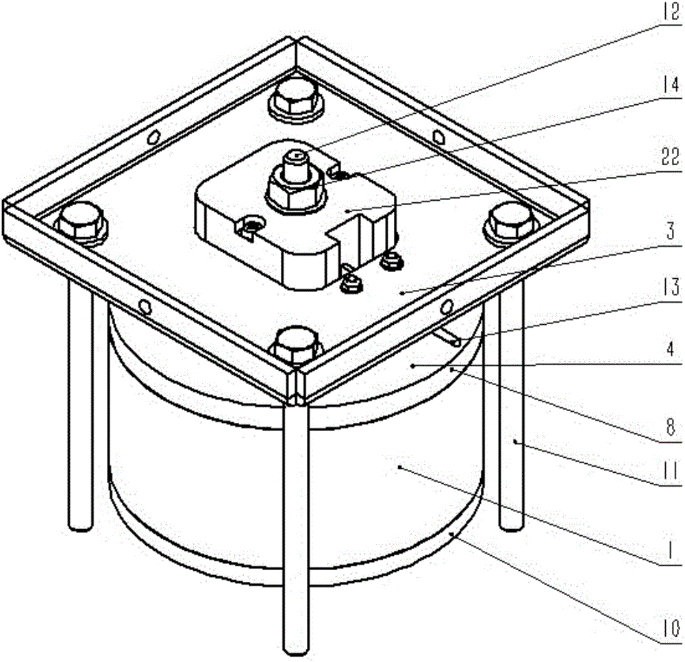
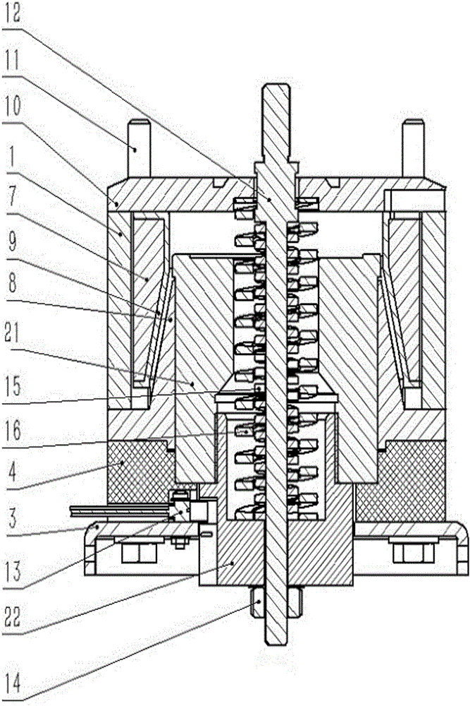
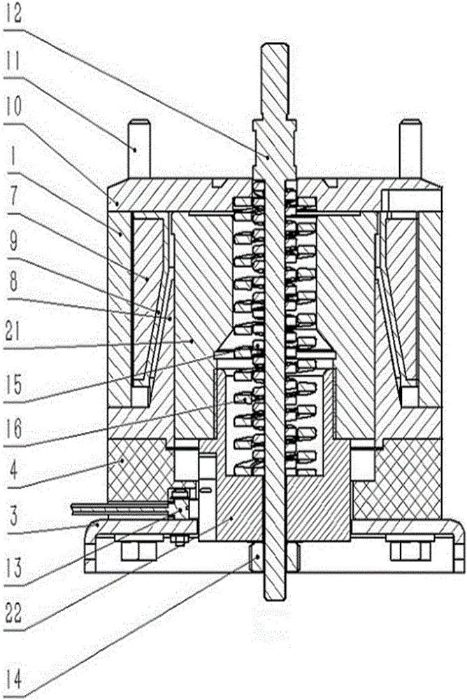
[0035] Such as Figure 1-3 As shown, in a specific embodiment, the single-phase magnetic holding operation mechanism of the present invention includes: an upper yoke 10, a magnetic sleeve 1, a lower yoke 8, a lower plastic end block 4, a coil 7, a moving iron core 21, Plastic cover 22, pull rod 12, opening spring 16 and closing pressure spring 15.

[0036] Such as Figure 2-3 As shown, the upper yoke 10, the magnetic sleeve 1 and the lower yoke 8 are arranged sequentially from top to bottom, and jointly enclose a magnetic field space; the coil 7 and the moving iron core 21 are respectively arranged in the magnetic field space; the lower plastic end The block 4 is fitted under the lower yoke 8, and the moving iron core 21 assembly is limited in the magnetic field space; one end of the plastic cover 22 is screwed to the moving iron core 21, and the other end extends away from the magnetic field space Lower plastic end block 4;

[0037] One end of the pull rod 12 passes throug...

Embodiment 2

[0042] Such as Figure 1-3As shown, in a specific embodiment, the present invention provides a single-phase magnetic holding operation mechanism, including an upper yoke 10, a lower yoke 8, a magnetic sleeve 1, a moving iron core assembly 2, and a lower plastic end block 4 and a metal fixed platen 3, a coil 7 is arranged between the upper yoke 10, the lower yoke 8 and the magnetic sleeve 1, and the moving iron core assembly 2 includes a moving iron core 21 and a plastic cover installed with threads on its lower part 22. The moving iron core 21 passes through the operation pull rod 12, the opening spring 16 and the closing pressure spring 15 in the middle, and the photoelectric sensing element 13 is embedded in the lower plastic end block 4, and the signal line of the photoelectric sensing element passes through the metal The groove between the fixed pressure plate 3 and the lower plastic end block 4 is drawn out, and the metal fixed pressure plate 3 is fixed and pressed to the...


PUM


Abstract

The invention provides a single-phase magnetic latching operating mechanism, relates to the field of a high-voltage switch, and aims to provide the single-phase magnetic latching operating mechanism which still can effectively complete operation latching in frequent operations. The single-phase magnetic latching operating mechanism provided by the invention comprises an upper magnetic yoke, a magnetic sleeve, a lower magnetic yoke, a coil and a movable iron core, wherein the upper magnetic yoke, the magnetic sleeve and the lower magnetic yoke are arranged in a fitted manner in the axis direction of the magnetic sleeve in sequence to form a magnetic field space in a joint surrounding manner; the coil and the movable iron core placed in the magnetic field space; and when the coil is charged, the movable iron core can move in a direction far from or close to the magnetic field space in the axis direction of the magnetic sleeve.

Description

technical field [0001] The invention relates to the field of high-voltage switches, in particular to a single-phase magnetic holding operating mechanism. Background technique [0002] In the field of high-voltage switches, the magnetic latching operating mechanism occupies an important position. At present, the magnetic latching operating mechanism on the market usually uses NdFeB permanent magnets to complete the operation and retention. However, due to the phenomenon of NdFeB demagnetization during operation, frequent operations are likely to cause mechanism failure. , It is very unfavorable for the control of high and low voltage lines. Contents of the invention [0003] The technical problem to be solved by the present invention is to provide a single-phase magnetic holding operation mechanism that can effectively complete operation holding under frequent operations. [0004] A single-phase magnetic holding operation mechanism of the present invention includes: an upp...

Claims


Application Information

Patent Timeline
Patent Type & Authority Applications(China)
IPC IPC(8): H01H3/28
CPCH01H3/28
Inventor 金钊
Owner ZHENJIANG SHISHENG ELECTRIC CO LTD
Learn More