
Neighboring grid power transmission line icing prediction method based on altitude factor

An altitude and transmission line technology, applied in the field of power transmission and distribution, can solve the problems of inability to identify small-scale icing of grids, inability to guide safe production of power grids, and coarse grid resolution.

Active Publication Date: 2016-12-07
STATE GRID HUNAN ELECTRIC POWER +2
View PDF2 Cites 5 Cited by
  • Summary
  • Abstract
  • Description
  • Claims
  • Application Information

AI Technical Summary

Problems solved by technology

However, due to the large prediction area and the coarse grid resolution of the existing numerical prediction models, it is impossible to identify the small-scale icing conditions in the grid
However, when the resolution is increased, the calculation time of the numerical prediction model will greatly exceed the forecast timeliness, and the forecast results cannot guide the safe production of the power grid.
It can be seen that under the current calculation conditions, the contradiction between forecast accuracy and forecast timeliness is irreconcilable, resulting in a large deviation between the icing forecast of some important transmission lines in the micro-topography and micro-meteorological area and the actual icing situation

Method used


Image

  • Neighboring grid power transmission line icing prediction method based on altitude factor
  • Neighboring grid power transmission line icing prediction method based on altitude factor
  • Neighboring grid power transmission line icing prediction method based on altitude factor

Examples


Embodiment 1

[0050] A method for predicting icing of adjacent grid transmission lines based on altitude factor, comprising the following steps:

[0051] (A) Numerical model grid setup. Set the numerical model prediction area range A (24°N-30°N, 109°E-114°E), divide the area range A into several square grids, and the resolution of the square grids is 0.25°×0.25°, Among them, there are 24 grids in latitude and 20 grids in area A, and the latitude and longitude of each grid point in area A is (a i , b j ), where a i is the longitude, b j For latitude, i=1...20, j=1...24;

[0052] (B) Grid point altitude calculation. According to the prediction area range A determined in step (A), collect digital elevation data (altitude elevation data) with a resolution of 30m×30m within the prediction area range A (24°N-30°N, 109°E-114°E) , and use the bilinear interpolation method to calculate the altitude of each grid point in the predicted area A;

[0053] (C) Neighboring grid parameter determinati...

Embodiment 2

[0089] Step (A) and (B) are with embodiment 1;

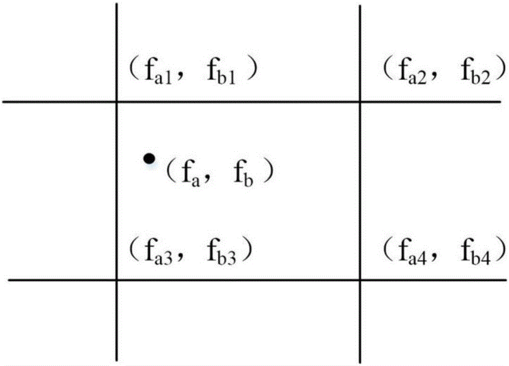
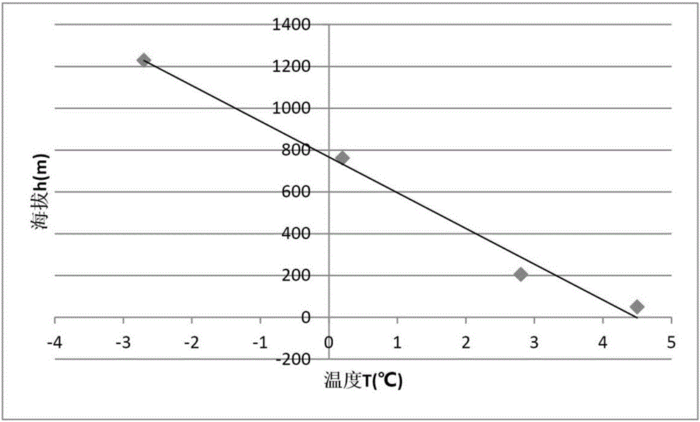
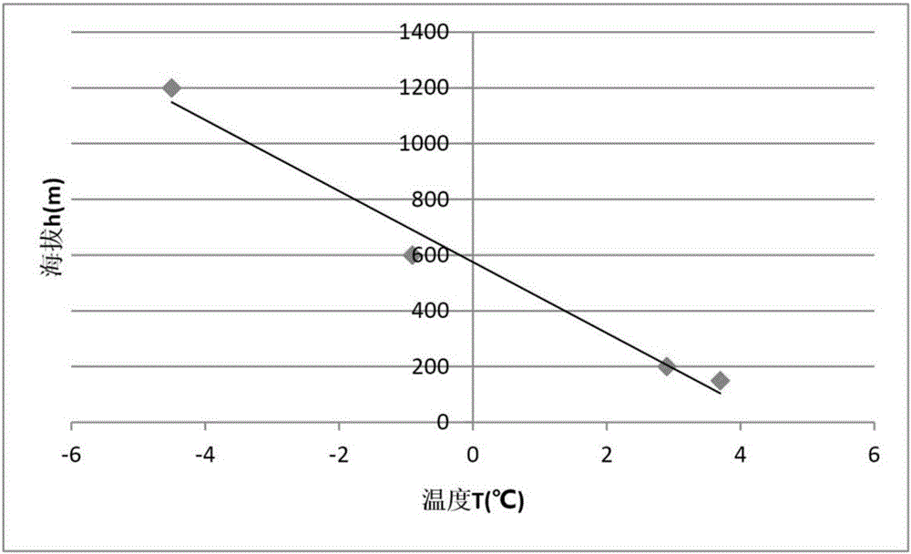
[0090] (C) Neighboring grid parameter determination. Determine the latitude and longitude (25.5424°N, 113.0623°E) of the prediction point of the transmission line, denoted as (f a , f b ), according to the altitude data collected in step (B) and the bilinear interpolation method, determine the point (f a , f b ) is recorded as H=430m; at the same time, according to the grid set in step (A), extract the point (f a , f b ) the latitude and longitude coordinates and altitudes of the four grid points around the grid, and the altitudes of the four grid points are recorded as H in order from small to large 1 、H 2 、H 3 、H 4 , where H 1 = 150m, H 2 = 200m, H 3 =600m,H 4 = 1200m, the latitude and longitude coordinates of the four grid points are recorded as (f a1 , f b1 ), (f a2 , f b2 ), (f a3 , f b3 ), (f a4 , f b4 );

[0091] (D) Sorting by altitude. Arrange the altitude of the predicted point in step (C) and the...


PUM


Abstract

The invention discloses a neighboring grid power transmission line icing prediction method based on an altitude factor. The method comprises the steps of setting a numerical mode grid, calculating the grid point altitude, determining neighboring grid parameters, ordering the altitude, predicting grid point icing, calculating the altitude of 0 DEG C and predicting icing of prediction points. The neighboring grid power transmission line icing prediction method based on the altitude factor has the advantages of being capable of predicting the icing situation of micro terrain areas, high in applicability, high in prediction accuracy and high in prediction efficiency.

Description

technical field [0001] The invention relates to the technical field of power transmission and distribution, in particular to a method for predicting icing of adjacent grid transmission lines based on an altitude factor. Background technique [0002] As the scale of the power grid continues to expand and the voltage level continues to increase, more and more transmission lines will inevitably pass through heavy ice areas, and icing on transmission lines is one of the important threats to the safe operation of the power grid. play an increasingly important role in the process. [0003] In recent years, with the rapid development of numerical computing technology, power grid icing prediction has changed from the traditional artificial prediction of a certain location relying on empirical formulas to the use of numerical prediction models to predict regions, which has significantly improved the automation level of power grid distribution prediction. However, due to the large pr...

Claims


Application Information

Patent Timeline
IPC IPC(8): G06Q10/04G06Q50/06
CPCG06Q10/04G06Q50/06
Inventor 陆佳政冯涛徐勋建李丽张杰杨莉
Owner STATE GRID HUNAN ELECTRIC POWER
Learn More