Oilfield RTU valve box electronic control integrated device
A valve chamber and electric control technology, applied in the direction of program control, computer control, general control system, etc., can solve the problems of non-reuse, long debugging time, high comprehensive investment, etc., shorten the construction period of the project, improve labor productivity, Reduce the effect of comprehensive investment
- Summary
- Abstract
- Description
- Claims
- Application Information
AI Technical Summary
Problems solved by technology
Method used
Image
Examples
Embodiment 2
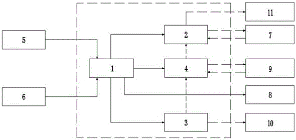
[0033] The power distribution unit 1 includes a backup power supply and a distribution cabinet, wherein the city power interface 5 is electrically connected to the distribution cabinet through the backup power supply, the backup power supply is provided with a mobile power generation equipment interface 6, and the city power interface 5 is connected to the 10 / 0.4kV city Electricity, the mobile power generation equipment interface 6 is connected to the mobile power generation equipment.
[0034] The backup power supply is a high-frequency switching power supply or UPS uninterruptible power supply.
[0035] This equipment is powered by dual power supply of 10 / 0.4kV city power and mobile power generation equipment. Under normal circumstances, it is powered by 10 / 0.4kV city power. power supply.
[0036] There is also a fan fixed in the box, which is electrically connected to the power distribution unit 1 in the box. The fan is an automatic temperature control fan to dissipate hea...
Embodiment 3
[0039] The communication unit 2 includes a network switch and an optical cable terminal box. The network switch is provided with working power by the power distribution unit 1. The optical cable terminal box is also connected to a superior dispatching interface 11 arranged on the box body. The superior dispatching interface 11 communicates with the superior station through optical fiber Connection, all production data and video signals of the RTU system of the instrument control unit 4 are connected to the network switch, and then uploaded to the superior station by the optical cable terminal box through the superior dispatching interface 11 through the optical cable.
[0040] The network switch is also provided with a communication device interface 7, which can realize the expansion of the communication device through the communication device interface 7. For example, a monitoring camera is also arranged in the casing, and the monitoring camera mechanism is electrically connect...
Embodiment 4
[0042] The RTU system of the instrument control unit 4 uploads relevant data to the superior station through the network switch of the communication unit 2 through the RJ45 interface and TCP / IP protocol, so as to realize the remote monitoring of the valve room.
[0043] The RTU system is connected to various monitoring equipment on site through the detection instrument and actuator interface 9 distributed on the box to realize remote monitoring. The main monitoring contents of the RTU system are as follows:
[0044] a) Process production process parameter monitoring
[0045] Ground temperature, pipeline surface temperature monitoring;
[0046] Pressure monitoring before and after the shut-off valve;
[0047] Remote control and valve position status monitoring of the shut-off valve in the valve chamber;
[0048] Combustible gas concentration monitoring in the valve block area.
[0049] b) Monitoring of internal parameters of the integrated electronic control device
[0050]...
PUM
 Abstract
Description
Claims
Application Information
 - R&D Engineer
- R&D Manager
- IP Professional
- Industry Leading Data Capabilities
- Powerful AI technology
- Patent DNA Extraction
Browse by: Latest US Patents, China's latest patents, Technical Efficacy Thesaurus, Application Domain, Technology Topic, Popular Technical Reports.
© 2024 PatSnap. All rights reserved.Legal|Privacy policy|Modern Slavery Act Transparency Statement|Sitemap|About US| Contact US: help@patsnap.com


