
Electrically-controlled dimming device

An electronically controlled adjustment and device technology, applied in the field of dimming, can solve problems such as poor effect and complicated process, and achieve the effect of simple structure, high transmittance, and easy industrial production

Inactive Publication Date: 2016-12-07
ZHANGJIAGANG KANGDE XIN OPTRONICS MATERIAL
View PDF8 Cites 5 Cited by
  • Summary
  • Abstract
  • Description
  • Claims
  • Application Information

AI Technical Summary

Problems solved by technology

[0005] It can be seen from the above that in the prior art, regarding electronically controlled dimming glass, negative liquid crystal materials are mostly used for surface orientation with PI solution, or trans PDLC is obtained by directional polymerization during polymer growth by stretching external force, but most of the processes are complicated. , poorly

Method used


Image

  • Electrically-controlled dimming device
  • Electrically-controlled dimming device
  • Electrically-controlled dimming device

Examples


Embodiment 1

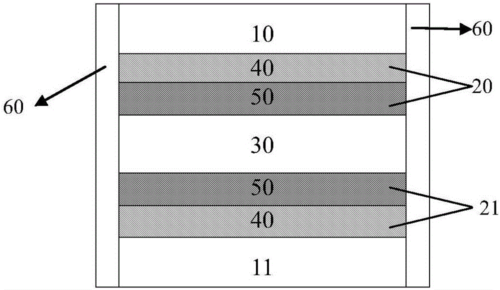
[0041] Such as figure 1 As shown, the present invention provides a reverse electronically controlled dimming device, including an upper transparent substrate 10, a first functional layer 20, an electrically controllable optical refractive index layer 30, and a second functional layer arranged sequentially from top to bottom. Layer 21, lower transparent substrate 11. The conductive layer 40 in the first functional layer 20 is arranged on the surface of the upper transparent substrate, and the microstructure layer 50 is arranged on the surface of the conductive layer; the conductive layer 40 in the second functional layer 21 is arranged on the surface of the lower transparent substrate, and the microstructure layer 50 is arranged on the surface of the transparent substrate. Layer 50 is sequentially disposed on the surface of the conductive layer. Wherein, the material of the layer capable of electrically controlling and adjusting the light refractive index is liquid crystal, a...

Embodiment 2

[0044] Such as figure 1 As shown, the present invention provides a formal electronically controlled dimming device, including an upper transparent substrate 10, a first functional layer 20, an electrically controllable optical refractive index layer 30, and a second functional layer arranged sequentially from top to bottom. 21. The lower transparent substrate 11. The conductive layer 40 in the first functional layer 20 is arranged on the surface of the upper transparent substrate, and the microstructure layer 50 is arranged on the surface of the conductive layer; the conductive layer 40 in the second functional layer 21 is arranged on the surface of the lower transparent substrate, and the microstructure layer 50 is arranged on the surface of the transparent substrate. Layer 50 is sequentially disposed on the surface of the conductive layer. Wherein, the material of the layer capable of electrically controlling and adjusting the light refractive index is liquid crystal, and ...

Embodiment 3

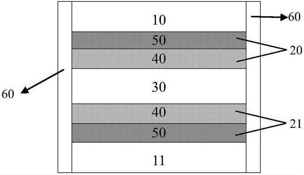
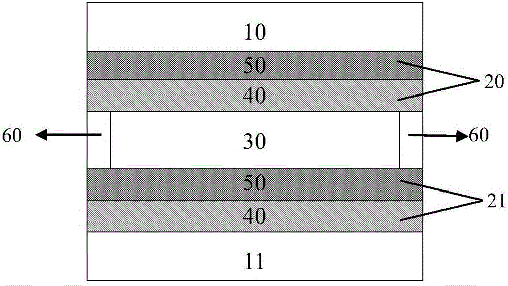
[0047] Such as figure 2 As shown, the present invention provides a reverse electronically controlled dimming device, including an upper transparent substrate 10, a first functional layer 20, an electrically controllable optical refractive index layer 30, and a second functional layer arranged sequentially from top to bottom. Layer 21, lower transparent substrate 11. The microstructure layer 50 in the first functional layer 20 is arranged on the surface of the upper transparent substrate, and the conductive layer 40 is arranged on the surface of the microstructure layer; the microstructure layer 50 in the second functional layer 21 is arranged on the surface of the lower transparent substrate, The conductive layer 40 is sequentially disposed on the surface of the microstructure layer. The liquid crystal is poured between the first functional layer 20 and the second functional layer 30 , and the two sides of the electronically controlled dimming device are sealed with a frame ...


PUM

PropertyMeasurementUnit
thicknessaaaaaaaaaa
thicknessaaaaaaaaaa
heightaaaaaaaaaa

Abstract

The invention discloses an electrically-controlled dimming device. The electrically-controlled dimming device comprises an upper transparent base material, a first functional layer, an electrically-controlled adjustable optical refractive index layer, a second functional layer and a lower transparent base material which are sequentially arranged, wherein each of the first functional layer and the second functional layer comprises a conducting layer, and at least one functional layer contains a microstructural layer; the electrically-controlled adjustable optical refractive index layer has the capability of converting the optical refractive index from n1 to n2 under the driving of voltage; the refractive index of the microstructural layer is n, and n is equal to n1 or n2. By controlling a switch of a power supply, the refractive index of the electrically-controlled adjustable optical refractive index layer is changed; by taking advantage of the difference between the refractive indexes of the microstructural layer and the electrically-controlled adjustable optical refractive index layer, when the refractive indexes are the same, a transparent state is presented, and when the refractive indexes are different, a hazy state is presented, so that switching from the transparent state to the hazy state is achieved and thus a dimming purpose is achieved. The electrically-controlled dimming device is simple in structure, easy in industrial production and good in conversion effect, and can arbitrarily adjust the haze according to needs.

Description

technical field [0001] The invention belongs to the technical field of light adjustment, and in particular relates to an electronically controlled light adjustment device. Background technique [0002] Polymer dispersed liquid crystal (polymer dispersed liquid crystal) is to mix low-molecular liquid crystals with prepolymers, and undergo polymerization reaction under certain process conditions to form micron-sized liquid crystal particles uniformly dispersed in a solid polymer matrix. The obtained liquid crystal particles have dielectric anisotropy. Under the condition of an external electric field, the polymer dispersed liquid crystal can realize the transition between transparent and opaque, so that the light transmittance of the film can be adjusted. [0003] Polymer dispersed liquid crystal technology has been widely used in electronically controlled dimming glass, holographic grating and many other technical fields. The product of polymer dispersed liquid crystal has t...

Claims


Application Information

Patent Timeline
Patent Type & Authority Applications(China)
IPC IPC(8): G02F1/1335
CPCG02F1/133504
Inventor 马文涛丁清华
Owner ZHANGJIAGANG KANGDE XIN OPTRONICS MATERIAL
Learn More