
Fault location system and method for collector line of offshore wind farm

A current collecting line and fault location technology, which is applied in the fault location, information technology support system, fault detection according to conductor type, etc., can solve the problems of special requirements for manufacturing and construction, large manpower and material resources investment, and long time consumption

Active Publication Date: 2019-04-26
NARI NANJING CONTROL SYST
View PDF5 Cites 0 Cited by
  • Summary
  • Abstract
  • Description
  • Claims
  • Application Information

AI Technical Summary

Problems solved by technology

This method is greatly affected by environmental factors and can only be tested after a complete power failure. The fault point is found slowly and the repair time of the fault is long, which is not conducive to the rapid restoration of power supply of the collector line.
In addition, for high-resistance faults, the existing technology needs to be equipped with a high-voltage generator, which makes on-site operation a potential safety hazard;
[0006] There is also the principle of using optical fiber temperature-sensing cables to measure temperature to realize online positioning of faulty collector lines, but this method needs to lay temperature-sensing cables on the entire collector line, which has special requirements for the production and construction of primary cables for collector lines , the construction is complicated and the economy is relatively poor;
[0007] Another method is to artificially open all the load switches on the collector line first, and then try to close them step by step until the circuit breaker jumps off. Although this method does not require the cooperation of any equipment, it is completely dependent on manually finding the fault area, manpower and material resources. Large investment, low efficiency, and long time consumption are not conducive to wind turbine grid-connected power generation

Method used


Image

  • Fault location system and method for collector line of offshore wind farm
  • Fault location system and method for collector line of offshore wind farm
  • Fault location system and method for collector line of offshore wind farm

Examples


Embodiment

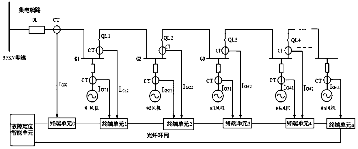
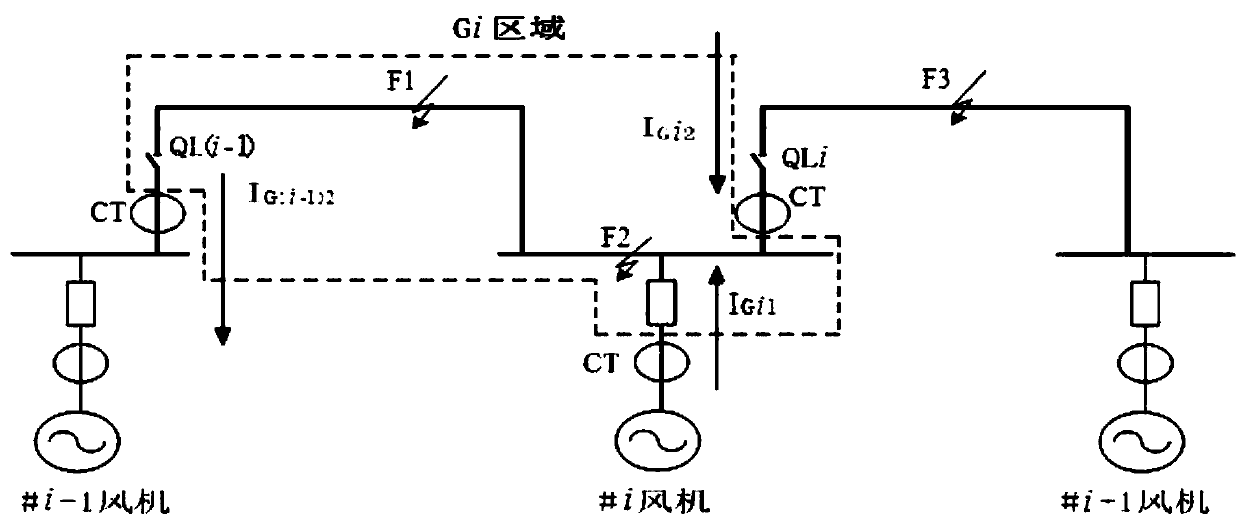
[0065] According to the installation position of the fan box figure 1 , 2 As an example, divide an offshore wind farm power collection line into several areas, that is, areas G1, G2...Gn; current terminal unit 0 collects the contact line CT on the contact line between the No. 1 wind box substation access point and the 35KV bus Current I G02 , the current terminal unit 1 collects the current I of the high-voltage side of the No. 1 fan contact box transformer G11 , collector line side current I G12 , the terminal unit 2 collects the high-voltage side current I of the No. 2 fan contact box transformer G21 , collector line side current I G22 , and so on, the terminal unit n collects the current I of the high-voltage side of the fan contact box transformer of number n Gn1 , collector line side current I Gn2 . Each current terminal unit converts the collected current analog signal into a digital signal through analog-to-digital conversion, and transmits the data to the fault ...


PUM


Abstract

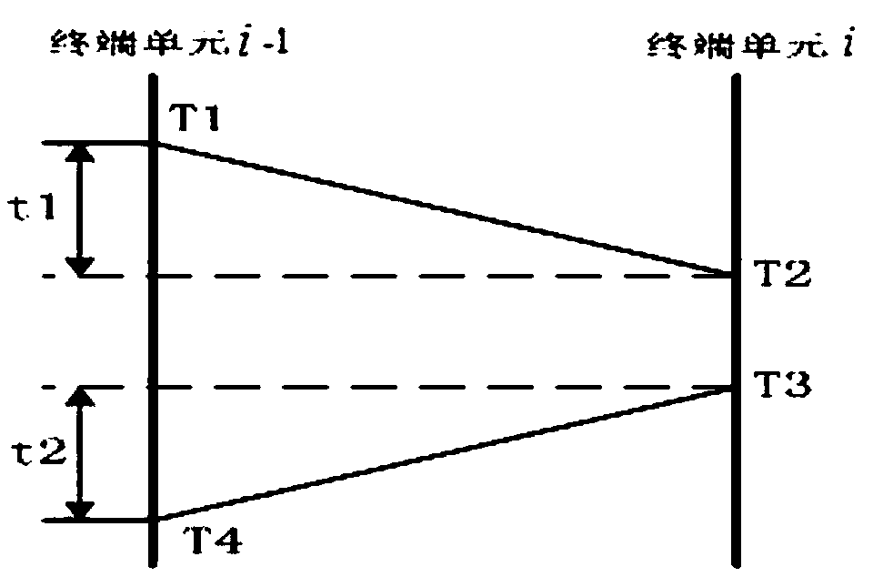
The invention discloses a system and a method of positioning offshore wind farm collecting power line fault. Current transformers are arranged on the offshore wind farm collecting power line according to wind turbine pre-fabricated substation access points; multiple terminal units are used for acquiring current data of pre-fabricated substation high voltage-side CTs and CTs on the collecting power line; a fault positioning intelligent unit at a booster station end carries out processing and judging; and a fault positioning result is obtained finally. During a data processing process, a network transmission model is used for determining the time difference between different current terminal units; synchronous processing and correction are carried out on the data through interpolation calculation; when a differential protection principle is then used for fault judgment, a tri-linear differential protection criterion is provided, unbalanced current and CT saturation situations in the normal case can be avoided, the relation between the differential current and the braking current is judged, and a fault area is determined. The offshore wind farm collecting power line fault can be quickly positioned, and while tripping is protected, the fault area is judged.

Description

technical field [0001] The invention relates to the technical field of safe operation of wind farms, in particular to a fault location system and method for collector lines of offshore wind farms. Background technique [0002] Refer to the accompanying drawings in the manual figure 1 As shown, the collection lines of offshore wind farms generally use a line connected to a wind turbine at intervals, and each wind turbine is equipped with a box-type transformer. A circuit breaker DL is installed between the collector line and the 35kV busbar of the step-up station, and a load switch QL is installed in the connecting line between the fan box transformers. When the collector line fails, the protection device installed at the circuit breaker trips the circuit breaker to isolate the fault. [0003] At present, there are mainly the following schemes for locating the fault area of ​​the collector line: [0004] One is the impedance method, that is, the DC bridge method. This met...

Claims


Application Information

Patent Timeline
Patent Type & Authority Patents(China)
IPC IPC(8): G01R31/08
CPCG01R31/085G01R31/088Y04S10/52
Inventor 吴仕平李永国葛军魏世贵许波
Owner NARI NANJING CONTROL SYST
Learn More