Matching device and method for heating parameters of thermal power generating unit
A technology for matching devices and thermal power units, applied in steam engine devices, steam generating devices, preheating, etc., can solve problems such as rising coal consumption for power supply, reduce heat consumption, improve boiler combustion, and reduce operating and equipment maintenance costs. Effect
- Summary
- Abstract
- Description
- Claims
- Application Information
AI Technical Summary
Problems solved by technology
Method used
Image

Examples
Embodiment 1
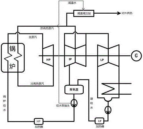
[0043] Such as Figure 4 and Figure 5 As shown, it is one of the implementations of the above-mentioned various technical solutions. The thermal power unit includes a boiler 1, a boiler superheater 2, a boiler reheater 3, a main steam pipeline 4, a steam turbine high-pressure cylinder 5, a cold reheat Steam pipeline, hot reheat steam pipeline, steam turbine medium pressure cylinder 51, steam turbine low pressure cylinder 52, generator 6, the steam output end of the boiler superheater 2 is connected to the steam turbine high pressure cylinder 5 through the main steam pipeline 4, and the steam turbine high pressure cylinder 5 passes through The cold re-steam pipeline is connected to the boiler reheater 3 in the boiler 1, and the boiler reheater 3 is connected to the steam turbine medium-pressure cylinder 51 and the steam turbine low-pressure cylinder 52 through the hot reheat steam pipeline. The pressure cylinder 51 and the steam turbine low-pressure cylinder 52 are connected ...
Embodiment 2
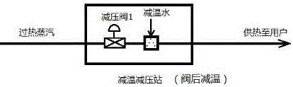
[0045] Such as Figure 4 and Image 6 As shown, it is one of the implementations of the above-mentioned various technical solutions. The thermal power unit includes a boiler 1, a boiler superheater 2, a boiler reheater 3, a main steam pipeline 4, a steam turbine high-pressure cylinder 5, a cold reheat Steam pipeline, hot reheat steam pipeline, steam turbine medium pressure cylinder 51, steam turbine low pressure cylinder 52, generator 6, the steam output end of the boiler superheater 2 is connected to the steam turbine high pressure cylinder 5 through the main steam pipeline 4, and the steam turbine high pressure cylinder 5 passes through The cold re-steam pipeline is connected to the boiler reheater 3 in the boiler 1, and the boiler reheater 3 is connected to the steam turbine medium-pressure cylinder 51 and the steam turbine low-pressure cylinder 52 through the hot reheat steam pipeline. The pressure cylinder 51 and the steam turbine low-pressure cylinder 52 are connected t...
Embodiment 3
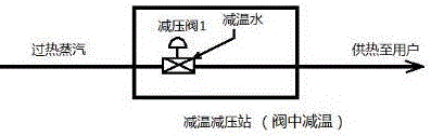
[0047] Such as Figure 4 and Figure 7 As shown, it is one of the implementations of the above-mentioned various technical solutions. The thermal power unit includes a boiler 1, a boiler superheater 2, a boiler reheater 3, a main steam pipeline 4, a steam turbine high-pressure cylinder 5, a cold reheat Steam pipeline, hot reheat steam pipeline, steam turbine medium pressure cylinder 51, steam turbine low pressure cylinder 52, generator 6, the steam output end of the boiler superheater 2 is connected to the steam turbine high pressure cylinder 5 through the main steam pipeline 4, and the steam turbine high pressure cylinder 5 passes through The cold re-steam pipeline is connected to the boiler reheater 3 in the boiler 1, and the boiler reheater 3 is connected to the steam turbine medium-pressure cylinder 51 and the steam turbine low-pressure cylinder 52 through the hot reheat steam pipeline. The pressure cylinder 51 and the steam turbine low-pressure cylinder 52 are connected ...
PUM
 Abstract
Description
Claims
Application Information
 - R&D
- Intellectual Property
- Life Sciences
- Materials
- Tech Scout
- Unparalleled Data Quality
- Higher Quality Content
- 60% Fewer Hallucinations
Browse by: Latest US Patents, China's latest patents, Technical Efficacy Thesaurus, Application Domain, Technology Topic, Popular Technical Reports.
© 2025 PatSnap. All rights reserved.Legal|Privacy policy|Modern Slavery Act Transparency Statement|Sitemap|About US| Contact US: help@patsnap.com