3D printing machine

A 3D printer and chassis technology, applied in the field of 3D printing, can solve the problems of replacing parts, short service life, manual focusing, etc., to increase the service life, improve the service life, and ensure the effect of printing quality.

Active Publication Date: 2016-12-07
GUANGZHOU HEYGEARS INTELLIGENT TECH CO LTD
View PDF5 Cites 4 Cited by
  • Summary
  • Abstract
  • Description
  • Claims
  • Application Information

AI Technical Summary

Problems solved by technology

[0002] Existing 3D printers are composed of an optical machine, a material tray, a forming platform, and a motor that drives the forming platform from bottom to top. The forming platform does not have a sensor system, so it is impossible to precisely control the printing process, and often When the forming platform and the material tray are peeled off, the printing fault is caused by too fast separation; in addition, the optical machine of the existing 3D printer is manually adjusted and locked on the chassis after the focus is fixed, while the locked fixed-focus light The precision of the 3D printer cannot be adjusted, so if you want to print a variety of products with different precision requirements, because the optical-mechanical focus corresponding to the products with different precision requirements is different, it limits the scope of use of the 3D printer, and the existing The light source of the optical machine is all visible light. This kind of visible light machine generates a lot of heat during the printing process, and the light intensity is not easy to control.
The overall service life of existing 3D printers is short, and parts often need to be replaced, which leads to high consumption costs

Method used


Image

  • 3D printing machine
  • 3D printing machine
  • 3D printing machine

Examples


Embodiment Construction

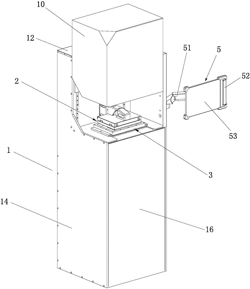
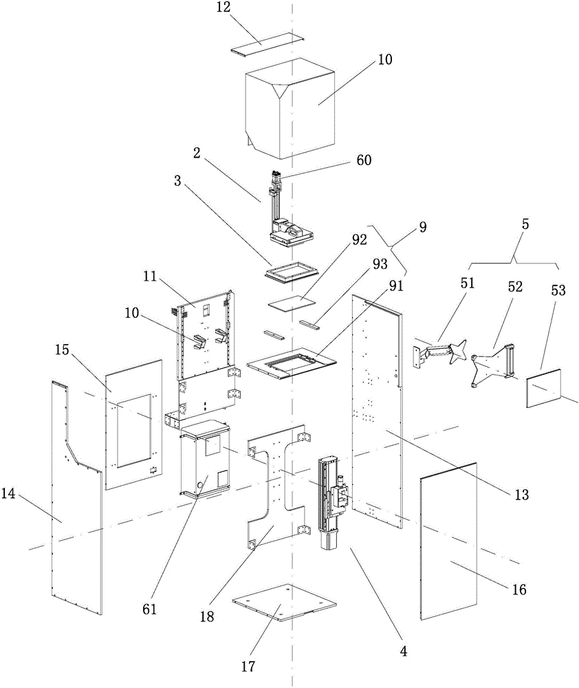
[0036] Such as Figure 1 to Figure 12 As shown, the 3D printer of the present invention is characterized in that it includes an organic case 1, a forming platform assembly 2 installed on the upper part of the case 1, a material tray 3, a dimmable machine assembly 4 installed on the lower part of the case 1, and an assembly installed outside the case 1. The control platform 5, the forming platform assembly 2 and the dimmable machine assembly 4 are all provided with a motor 60, the forming platform assembly 2 is provided with a force feedback system, and the motor 60 and the force feedback system are all connected to the control platform 5 The control system is electrically connected, so the control system and the force feedback system can cooperate with each other to realize effective control of the lifting speed of the forming platform 21.

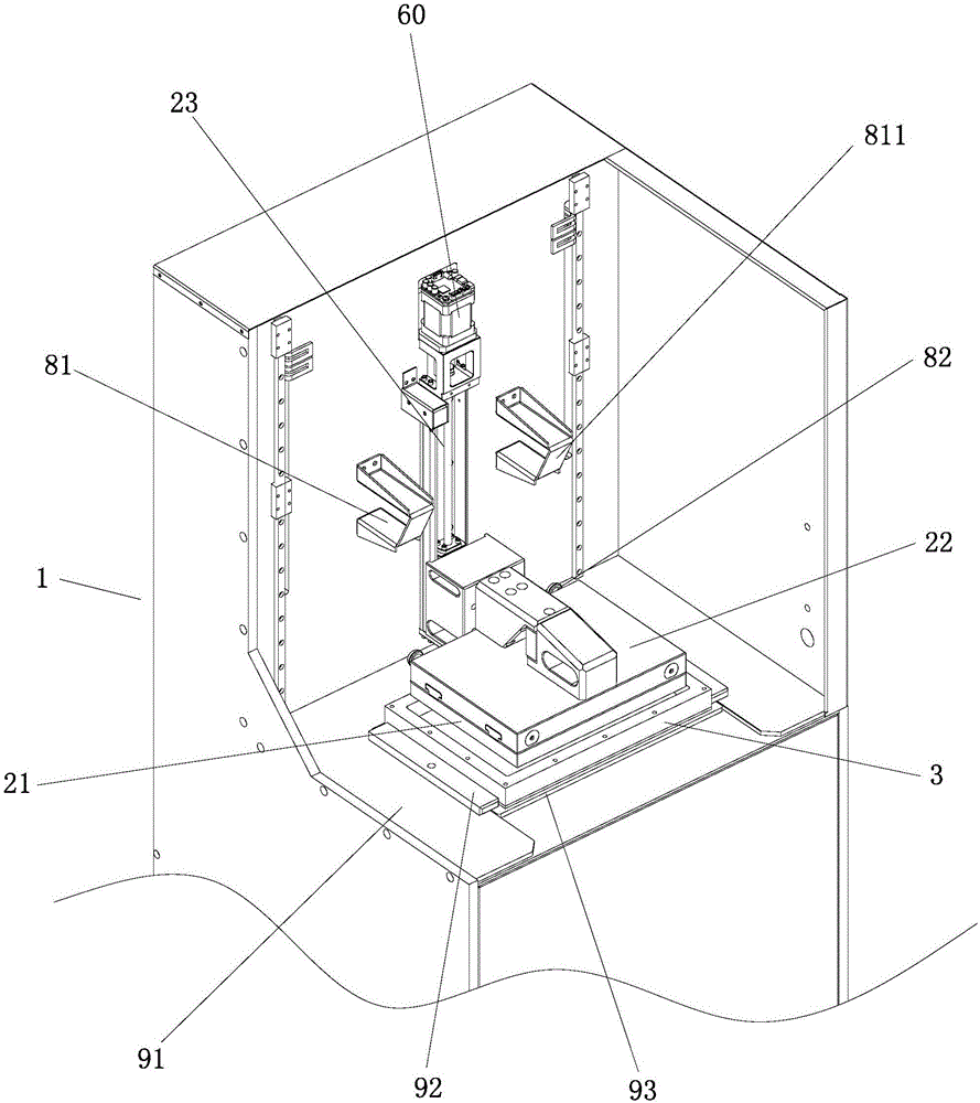
[0037] Such as figure 2 As shown, the cabinet 1 of this embodiment includes an upper part and a lower part, and a transparent interlaye...


PUM

PropertyMeasurementUnit
wavelengthaaaaaaaaaa

Abstract

The invention discloses a 3D printing machine. The 3D printing machine comprises a machine box, a forming platform assembly mounted at the upper part of the machine box, a material disc, an adjustable optimal machine assembly mounted at the lower part of the machine box, and a control platform mounted outside the machine box, wherein the forming platform assembly and the adjustable optimal machine assembly are provided with motors; a force feedback system is arranged on the forming platform assembly; and the motors and the force feedback system are electrically connected with a control system of the control platform, so that the lifting speed of a forming platform can be effectively controlled through the mutual cooperation of the control system and the force feedback system. According to the 3D printing machine, an optical machine at the lower part of the machine box is designed as the adjustable optimal machine assembly, the up-and-down motion of the optical machine is controlled through an adjusting device, the focal length is adjustable, and the 3D printing machine is applicable to printing of various breadths and is applicable to printing of printing products of various precision as well.

Description

technical field [0001] The invention relates to the technical field of 3D printing, in particular to a 3D printer. Background technique [0002] Existing 3D printers are composed of an optical machine, a material tray, a forming platform, and a motor that drives the forming platform from bottom to top. The forming platform does not have a sensor system, so it is impossible to accurately control the printing process, and often When the forming platform and the material tray are peeled off, the printing fault is caused by too fast separation; in addition, the optical machine of the existing 3D printer is manually adjusted and locked on the chassis after the focus is fixed, while the locked fixed focus light The precision of the 3D printer cannot be adjusted, so if you want to print a variety of products with different precision requirements, because the optical-mechanical focus corresponding to the products with different precision requirements is different, it limits the scop...

Claims


Application Information

Patent Timeline
Patent Type & Authority Applications(China)
IPC IPC(8): B29C67/00B33Y30/00B33Y50/02
CPCB33Y30/00B33Y50/02
Inventor 黄鹤源桂培炎江浩许桂鑫罗观
Owner GUANGZHOU HEYGEARS INTELLIGENT TECH CO LTD
Why Eureka
Try Eureka