Clip-on chuck

A clamp-type, chuck technology, applied in the direction of the chuck, can solve the problems of inability to realize double-sided simultaneous processing, long spindle box, low efficiency, etc., to achieve a wide range of applications, increase clamping space, and high efficiency Effect

Active Publication Date: 2018-08-03
CHANGZHOU BEIDEFU MACHINERY SCI & TECH
View PDF14 Cites 0 Cited by
  • Summary
  • Abstract
  • Description
  • Claims
  • Application Information

AI Technical Summary

Problems solved by technology

[0003] The technical problem to be solved by the present invention is: in order to solve the problem that the original spindle box is too long to realize double-sided simultaneous processing, and the efficiency is low, the present invention provides a chuck type chuck, which can hold the workpiece to be processed Pass through the pull rod, and then move the pull rod to the left and right to drive the jaws to move to the center of the chuck to complete the purpose of clamping and loosening the workpiece, and then can perform single-sided processing or two-way processing, with high efficiency and powerful functions

Method used


Image

  • Clip-on chuck
  • Clip-on chuck
  • Clip-on chuck

Examples


Embodiment Construction

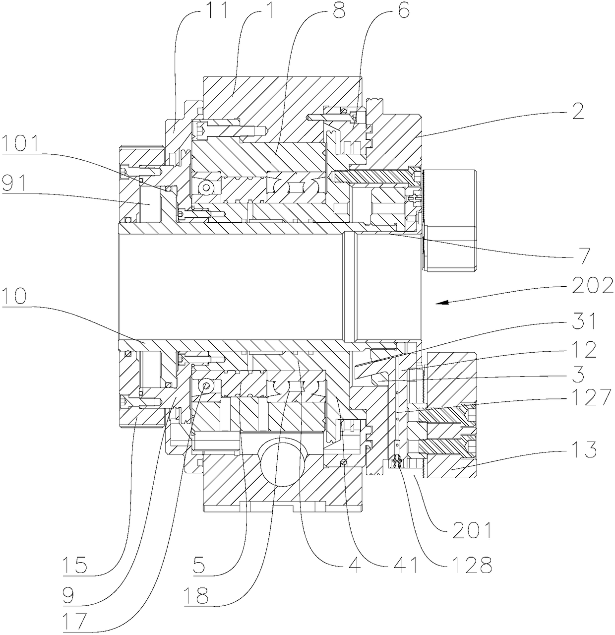
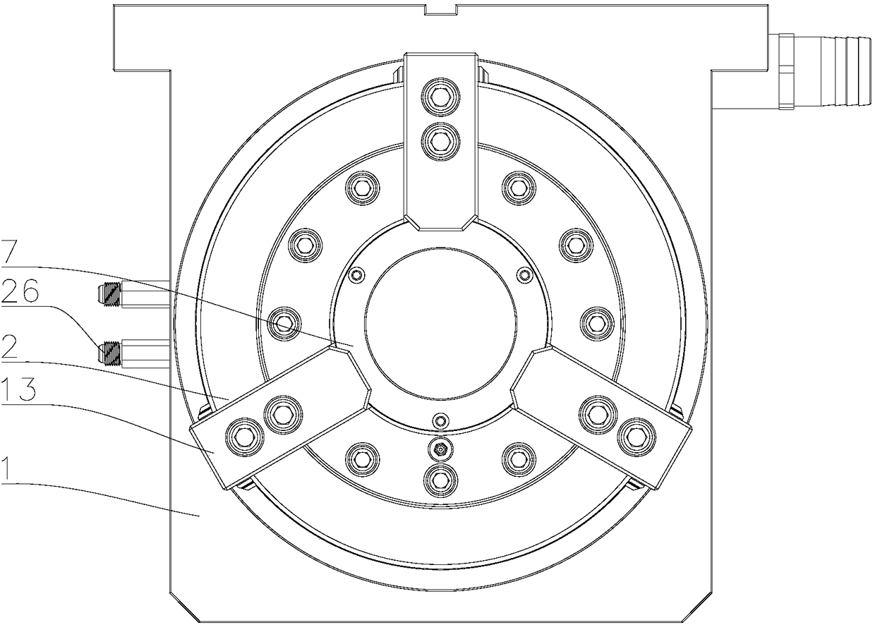
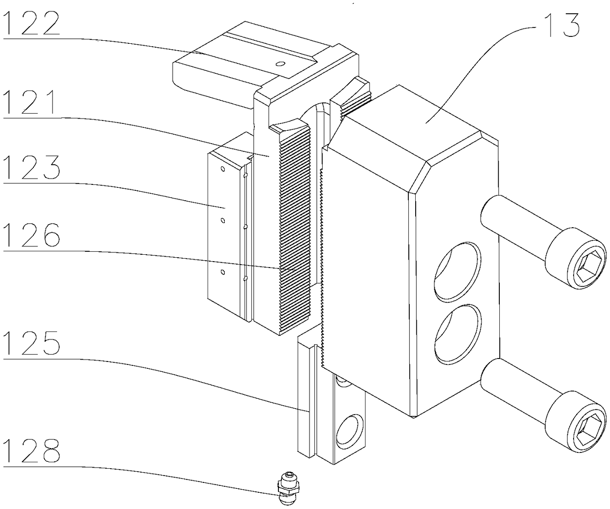
[0026] The present invention is described in further detail now in conjunction with accompanying drawing. These drawings are all simplified schematic diagrams, which only illustrate the basic structure of the present invention in a schematic manner, so they only show the configurations related to the present invention. The F direction is the upward direction, the opposite direction is the downward direction, and the plane perpendicular to the F direction is the horizontal plane.

[0027] A chuck type chuck, such as Figure 1-4 shown, including:

[0028] The disc body 2 is provided with at least two T-shaped grooves 201 in the horizontal direction, and the center of the disc body 2 has a shaft hole 202,

[0029] Claws, the claws include a fixed bottom claw 12 and an upper claw 13, the bottom claw 12 includes a bottom claw plate 121 and a side plate 122 with an angle of less than 90° with the bottom claw plate 121, and the bottom claw plate 121 has a The T-shaped groove 201 m...


PUM


Abstract

The invention relates to the technical field of machine tool fixtures, in particular to a holder type chuck. According to the holder type chuck, at least two T-shaped grooves in the horizontal direction are formed in a chuck body; a shaft hole is formed in the center of the chuck body; clamping jaws include the bottom jaws and the upper jaws, wherein the bottom jaws and the upper jaws are fixedly arranged. Each bottom jaw comprises a bottom jaw plate and a side plate. The included angle between each bottom jaw plate and the corresponding side plate is smaller than 90 degrees. Bottom jaw slide blocks are arranged on the bottom jaw plates. At least two obliquely-formed oblique grooves matched with the side plates in shape are formed in a wedge-shaped sleeve. The included angle between the oblique grooves and the axis of the oblique sleeve is equal to the included angle between the bottom jaw plates and the side plates. The clamping jaws are arranged in the T-shaped grooves through the bottom jaw slide blocks in a sliding manner. The side plates are arranged in the oblique grooves of the wedge-shaped sleeve. A pull rod is fixedly arranged on the wedge-shaped sleeve. The holder type chuck is provided, the pull rod can penetrate workpieces needing to be machined, then, the clamping jaws are driven to move towards the center of the chuck by moving the pull rod downwards, and clamping of the machined workpieces is completed; and because the total length of the holder type chuck is small, the function of conducting machining on two sides at the same time can be achieved, and efficiency is high.

Description

technical field [0001] The invention relates to the technical field of machine tool fixtures, in particular to a clamp-type chuck. Background technique [0002] The headstock of the existing chuck type chuck is too long to realize double-sided simultaneous processing, and the efficiency is low. The overall length of the chuck is short, which can realize double-sided simultaneous processing of shaft parts in one clamping, which greatly improves production efficiency. It has many advantages such as light body, convenient installation, small space occupation, and wide application range. Contents of the invention [0003] The technical problem to be solved by the present invention is: in order to solve the problem that the original spindle box is too long to realize double-sided simultaneous processing, and the efficiency is low, the present invention provides a chuck type chuck, which can hold the workpiece to be processed Pass through the pull rod, and then move the pull ro...

Claims


Application Information

Patent Timeline
Patent Type & Authority Patents(China)
IPC IPC(8): B23B31/16B23B31/30
CPCB23B31/16B23B31/16008B23B31/30
Inventor 孙贤青孙贤良李传飞刘小成
Owner CHANGZHOU BEIDEFU MACHINERY SCI & TECH
Why Eureka
Try Eureka