
Altitude rescue device

A life-saving device and inflatable bag technology, applied in life-saving equipment, building rescue and other directions, can solve the problems of high hydrogen consumption and poor rescue effect, and achieve the effect of reducing the risk of injury, saving the amount of use, and avoiding bumps.

Active Publication Date: 2019-04-12
振林建设集团股份有限公司
View PDF10 Cites 0 Cited by
  • Summary
  • Abstract
  • Description
  • Claims
  • Application Information

AI Technical Summary

Problems solved by technology

[0005] Therefore, the technical problem to be solved by the present invention is to overcome the defects of poor rescue effect and large hydrogen consumption of the high-altitude life-saving device in the prior art, thereby providing a high-altitude life-saving device with good rescue effect and low hydrogen consumption

Method used


Image

  • Altitude rescue device
  • Altitude rescue device

Examples


Embodiment 1

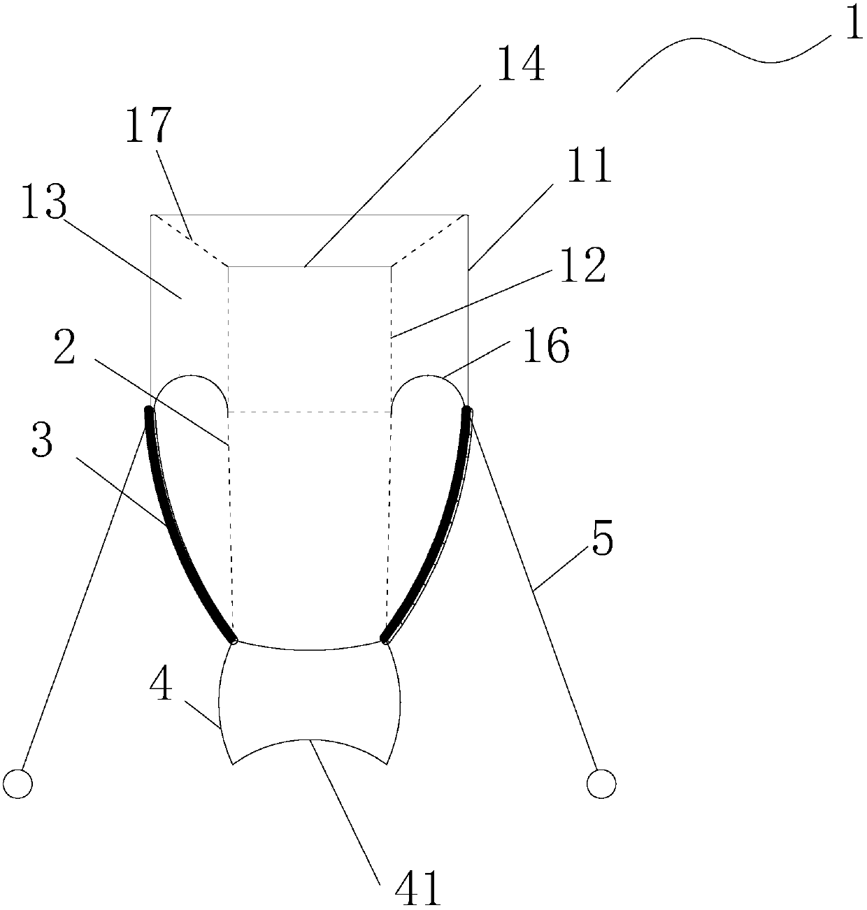
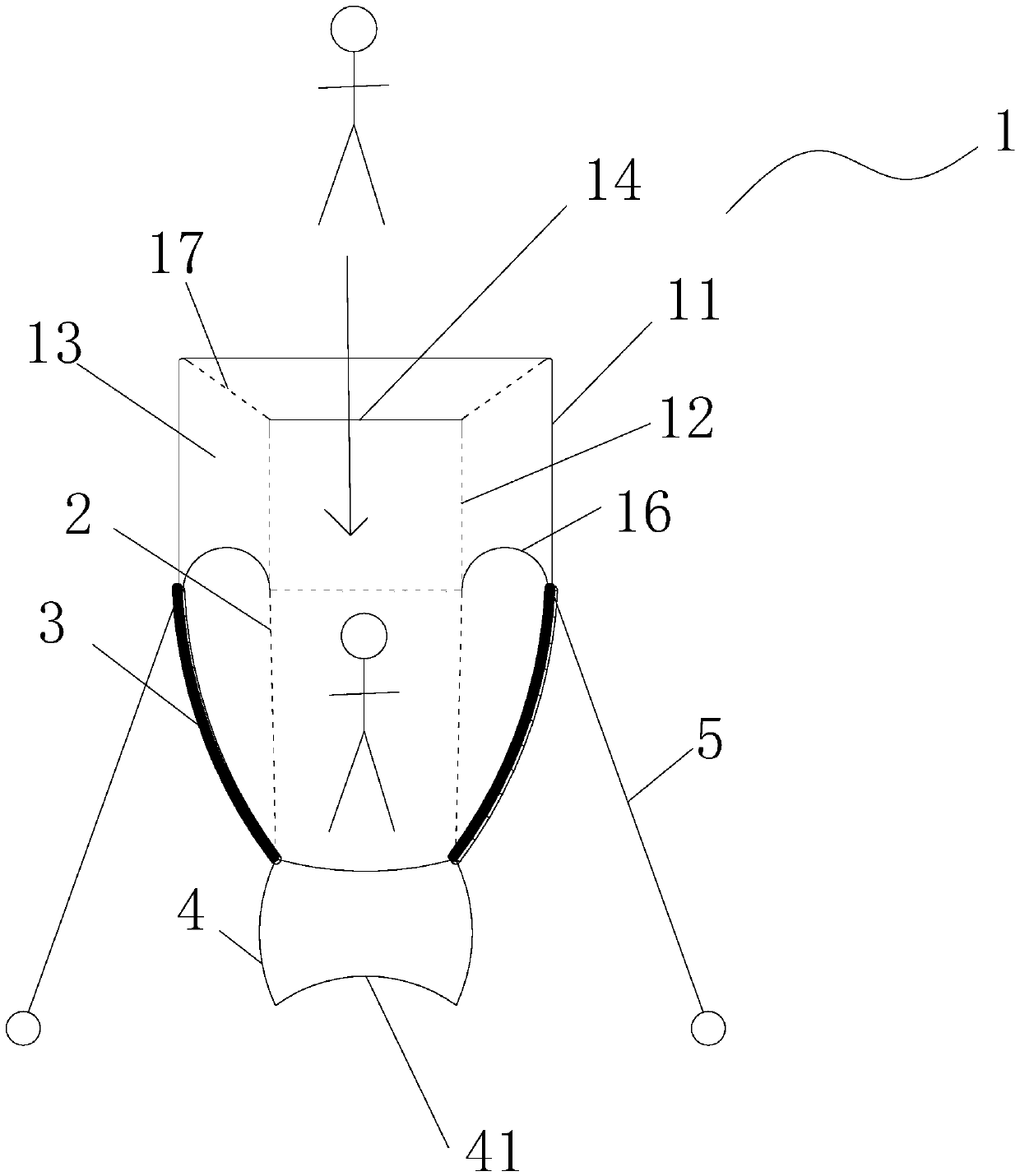
[0035] Such as figure 1 and figure 2 As shown, this embodiment provides a high-altitude lifesaving device, which includes an inflatable bag 1 located above and a jumping bag 2 located below. in,

[0036] The inflatable bag 1 includes an outer layer structure 11 and an inner layer structure 12. Between the outer layer structure 11 and the inner layer structure 12 is an inflatable cavity 13 filled with buoyancy gas. Through the inflatable cavity 13, the high-altitude lifesaving device can be floated to a high altitude. Carrying out rescue work indirectly reduces the jumping height of escapees from high altitude; the top of the inflatable bag 1 is provided with a jump entrance 14 for escapees to jump into, and the jump entrance 14 communicates with the guide cavity formed inside the inner structure 12, and jumps The entry bag 2 is connected to the bottom of the guide chamber, and the guide chamber can help the escapee jump smoothly into the jump-in bag 2 through the jump entra...

Embodiment 2

[0047] As a modification of the high-altitude lifesaving device in Embodiment 1, this embodiment provides a high-altitude lifesaving device, which differs from the high-altitude lifesaving device in Embodiment 1 in that:

[0048] In this embodiment, the inflatable bag 1 of the high-altitude lifesaving device includes a plurality of jump openings 14 and guide cavities independently arranged along the horizontal direction, and a plurality of jump-in bags 2 are connected below the plurality of guide cavities. Through the above-mentioned settings, the The high-altitude lifesaving device can rescue many people at one time, and a plurality of jumping entrances 14, guide chambers and jumping bags 2 are separated from each other, which avoids bumping and hurting each other among the survivors.


PUM


Abstract

The invention provides a high-altitude lifesaving device. The high-altitude lifesaving device comprises an inflation bag, a jumping-in bag and a pull rope. An inflation cavity inflated with buoyancy gas is formed between an outer-layer structure and an inner-layer structure. A jumping-in opening is formed in the top of the inflation bag and communicates with a guiding cavity formed in the inner-layer structure. A traction rope is connected between the edge of the bottom end of the jumping-in bag and the edge of the bottom end of the outer-layer structure of the inflation bag. After an escaper jumps in the jumping-in bag, the traction rope is stretched under the gravity action of the escaper, the traction rope downwards pulls the bottom end of the outer-layer structure of the inflation bag, and therefore an umbrella-shaped first arc face is formed on the position, between the bottom end of the outer-layer structure of the inflation bag and the bottom end of the inner-layer structure of the inflation bag, of the lower surface of the inflation bag. The lower portion of the jumping-in bag is connected with a buffering air bag inflated with the buoyancy gas. The pull rope is connected with the traction rope through a pulley structure, the traction rope is connected to the edge of the bottom end of the outer-layer structure of the inflation bag, and through the pulley structure, the pull rope can make the jumping-in bag ascend or descend relative to the inflation bag through downward pulling or upward loosening.

Description

technical field [0001] The invention relates to the technical field of safety lifesaving equipment, in particular to a high-altitude lifesaving device. Background technique [0002] With the expansion of city scale and the increasing number of high-rise buildings, the safe escape of people living and working in high-rise buildings has become an important issue when an emergency occurs. There are many inventions involving high-altitude life-saving devices, mainly using rope basket life-saving devices, Anti-fall air cushions, deceleration glide passages and other types, these devices have good effects, but some are bulky and expensive, and some are complicated to install and delay time. [0003] For this reason, prior art discloses a kind of aerial life-saving device as the Chinese patent document that the authorized announcement number is CN2734255Y, and the structure of this aerial life-saving device is: the air bag is equipped with at the top of the housing, handle is equip...

Claims


Application Information

Patent Timeline
Patent Type & Authority Patents(China)
IPC IPC(8): A62B1/22
CPCA62B1/22
Inventor 王海龙
Owner 振林建设集团股份有限公司
Learn More