
Magnetic epilator

An actuator and roller technology, applied in clothing, hairdressing equipment, perming hair roots, etc., can solve the problems of cancellation of mobility, inefficiency of clamps, unequal distribution, etc., and achieve the effect of reducing volume

Active Publication Date: 2016-11-30
SEB SA
View PDF5 Cites 0 Cited by
  • Summary
  • Abstract
  • Description
  • Claims
  • Application Information

AI Technical Summary

Problems solved by technology

However, this configuration has the disadvantage of having a statically indeterminate assembly that results in at least some degree of mobility of each movable leaf being canceled several times
In other words, the rigid connection of a plurality of movable lamellae to each other, at least during closing, leads to an unequal distribution of the overall force for each clamp, according to the differences and characteristics (diameters) of the hairs to be plucked, so that all clamps Clamps do not have the same efficiency

Method used


Image

  • Magnetic epilator
  • Magnetic epilator
  • Magnetic epilator

Examples


Embodiment Construction

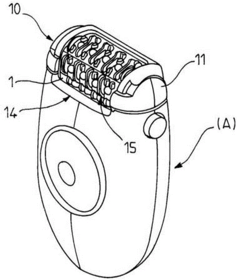
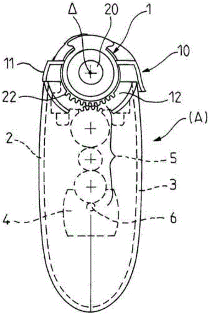
[0042] Such as figure 1 and figure 2 As shown, the present invention relates to an electric depilatory device (A), which comprises a hollow housing consisting of two half housings 2 and 3, the two The half-shells 2 and 3 together define a grip area on the one hand and a closed housing on the other hand, which holds the different functional elements constituting the device, such as the The motor 4, the transmission mechanism 5 transmits the rotational movement of the output gear 6 of the motor 4. According to the illustrated embodiment, said transmission mechanism 5 comprises a gear set whose axis is parallel to the axis of rotation of said electric motor.

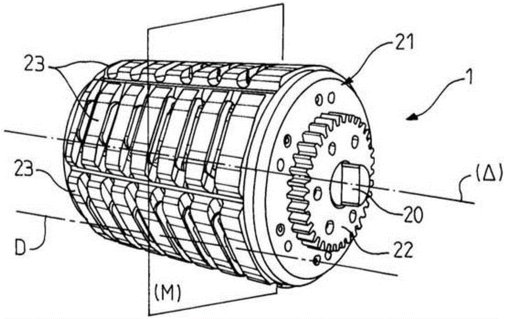
[0043] The housing is equipped with a connector 10 for body care, the connector 10 being a depilatory head 10 comprising a hollow body 11 defining a depilatory chamber 12 inside which a depilatory head is arranged The cylinder 1 of the depilatory head is exposed at the window 14 arranged in the hollow body 11 . The cyl...


PUM


Abstract

The invention relates to a roller (1) of an epilator head for a motorised epilator, including: a stationary central shaft intended for being rotatably connected to a housing of the epilator; a tubular cage which is rotatably movable about the central shaft and intended for being rotated by a motor of the apparatus and which supports at least one row of tweezers (15) each formed by a stationary blade rigidly connected to the tubular cage and a blade that is moveable between an open position in which the movable blade is separated from the stationary blade and a closed position in which the movable blade is in contact with the stationary blade; control means for moving the movable blades between the open and closed positions thereof during the rotation of the tubular cage about the central shaft, said control means including actuators intended for moving said movable blades using magnetic forces. According to the invention, the moving means include, for each movable blade, an individual leg which is translatably connected to said blade and which is intended for interacting with at least one actuator, at least in order to close the movable blade.

Description

technical field [0001] The present invention relates to the technical field of depilatory devices for plucking hair, in particular to the field of depilatory devices equipped with plucking tongs. Background technique [0002] An epilation head for an epilation device having plucking tongs comprising a drum mounted rotatably about its longitudinal axis is known as described in patent application EP2227110 filed by the present inventor. The drum comprises a plurality of peripheral rows of plucking tongs, each formed of at least one movable flap which cooperates alternately with its opposite support surface to clamp and then release the hairs. The drum also includes a tubular sleeve carrying extraction tongs, the tubular sleeve being coaxial with a central shaft, the central shaft including at least one cam groove, the at least one cam groove A guide path is formed for the movable sheet during rotational movement of the roller sleeve relative to the central shaft. A periphera...

Claims


Application Information

Patent Timeline
IPC IPC(8): A45D26/00
CPCA45D26/0028
Inventor 法比安·诺曼德弗兰克·曼迪卡卡米尔·吉罗
Owner SEB SA
Learn More