Water pressure energy storage mechanism of toilet bowl
A toilet and water pressure technology, applied in the field of sanitary ware, can solve the problems of limited installation position and operable space, restrictions on popularization and application, and large volume of the floating tank, and achieve simple structure, large force, and small volume Effect
- Summary
- Abstract
- Description
- Claims
- Application Information
AI Technical Summary
Problems solved by technology
Method used
Image


Examples
Embodiment 1
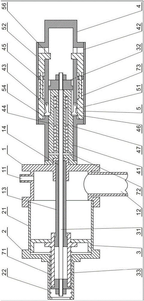
[0032] refer to figure 1 , the present invention includes:
[0033] One is provided with the water inlet 11, the water outlet 12 is provided with the seal rod 13 in the axial direction, and the cylinder block 1 with the first piston rod hole 14 is provided at the center of the seal rod 13 axis;
[0034] A piston cylinder 2 axially provided with a piston cylinder 21, a piston guide cylinder 22 and axially connected to one end of the cylinder seat 1;
[0035] One is provided with a piston rod 31, one end is provided with a briquetting block 32, the other end is provided with a guide cylinder 33 and the piston 3 is located in the piston cylinder 2;
[0036] One is equipped with a power slider 41, a slider lock seat 42 and a bracket 4 axially connected with the other end of the cylinder seat 1, and the slider lock seat 42 is provided with a bolt hinge seat 43 and a spring seat 45, and the power slider The block 41 is provided with a spring hole 44, a lock groove 46 and a second ...
specific Embodiment
[0043] refer to figure 1 , figure 2 , the present invention is used in connection with the suction and sewage device 8 of the toilet, and the pull rope 81 of the suction and sewage device 8 of the toilet is connected with the power slider 41 of the present invention through a pulley 82 . A drain valve is connected to the drain port 12 of the present invention, a water inlet valve is connected to the water inlet 11, and a drain button is arranged on the drain valve, and the closing control lever of the water inlet valve switch and the drain valve is installed on the power slider of the bracket 4 41 stroke limit, the working process of the present invention is as follows:
[0044] Flushing procedure: see figure 1 , figure 2 , manually press the drain button of the toilet, the drain valve on the drain port 12 is opened, the water in the piston cylinder 21 is discharged from the drain port 12, and as the water in the piston cylinder 21 is discharged, the force of the water on...
Embodiment 2
[0047] refer to figure 1 , 2 , the present invention provides a water pressure energy storage mechanism of a toilet, which is used to control the suction and sewage device of the toilet, including a piston cylinder and a control part; the present invention uses tap water pressure to push the piston to compress the spring and convert it into elastic potential energy , and the suction and sewage device of the toilet is controlled by releasing the elastic potential energy to drive the power slider.
[0048] Specifically, the hydraulic energy storage mechanism of the toilet includes a piston cylinder 2, and the piston cylinder 2 is composed of a cylinder body 21, a cylinder body seat 1 and a piston guide cylinder 22; both axial ends of the cylinder body 21 are open, and the piston guide The cylinder 22 cover is arranged on the opening of one end of the cylinder body 21, and the cylinder body seat 1 is arranged on the opening of the other end of the cylinder body 21; of course, th...
PUM
 Abstract
Description
Claims
Application Information
 - R&D
- Intellectual Property
- Life Sciences
- Materials
- Tech Scout
- Unparalleled Data Quality
- Higher Quality Content
- 60% Fewer Hallucinations
Browse by: Latest US Patents, China's latest patents, Technical Efficacy Thesaurus, Application Domain, Technology Topic, Popular Technical Reports.
© 2025 PatSnap. All rights reserved.Legal|Privacy policy|Modern Slavery Act Transparency Statement|Sitemap|About US| Contact US: help@patsnap.com