Data transmission method, receiving signal detection method and device, and data transmission sending device

A technology of data transmission and layer data, which is applied in the direction of digital transmission system, separation device of transmission path, transmission system, etc. It can solve the problems of overlapping modulation constellation diagrams and inability to effectively detect signals at the receiving end, and achieve the effect of improving system performance

Active Publication Date: 2016-11-23
DATANG MOBILE COMM EQUIP CO LTD
View PDF5 Cites 20 Cited by
  • Summary
  • Abstract
  • Description
  • Claims
  • Application Information

AI Technical Summary

Problems solved by technology

[0007] Embodiments of the present invention provide a method and device for data transmission and received signal detection to solve the problem in the prior art that the modulation symbols of multi-layer data streams using the same modulation constellation and the same power experience the same channel in the PDMA coding matrix When arriving at the receiving end, the corresponding modulation constellations overlap, and the receiving end cannot effectively detect the signal

Method used


Image

  • Data transmission method, receiving signal detection method and device, and data transmission sending device
  • Data transmission method, receiving signal detection method and device, and data transmission sending device
  • Data transmission method, receiving signal detection method and device, and data transmission sending device

Examples


example 1

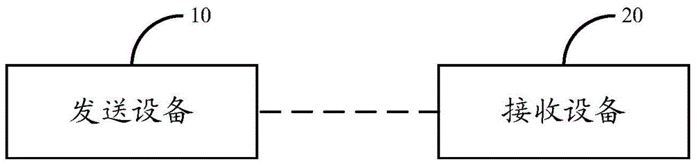
[0092] Example 1. Use Realize two-terminal transmission.

[0093] The encoding matrix is:

[0094]

[0095] The coding matrix given in the above formula is allocated to two terminals, where the column in the coding matrix corresponds to the data layer l of terminal k, and the row corresponds to the frequency domain logic resource m, that is, the first, second, and third columns correspond to the data of terminal 1 Layer, columns 4, 5, and 6 correspond to the data layer of Terminal 2.

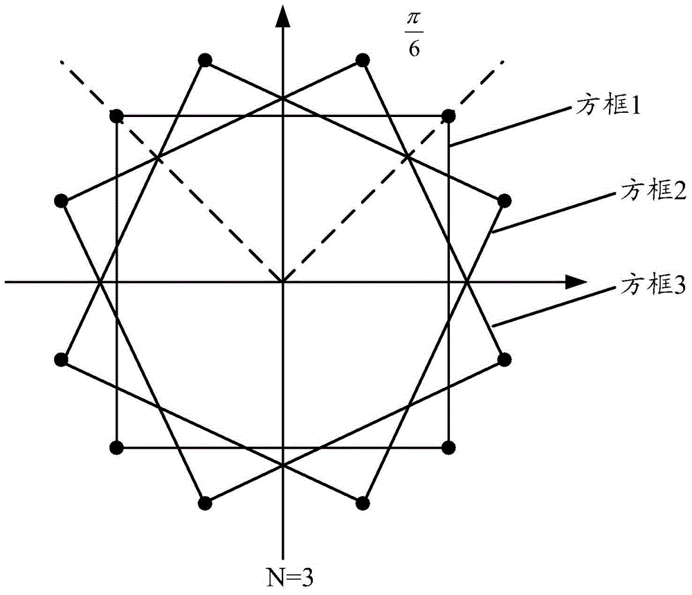
[0096] During downlink transmission, terminal 1 and terminal 2 occupy 6 data layers in total, and they reach any terminal through the same channel. The weight of each row of the 6-layer data of the encoding matrix is ​​3, that is, the number of phase rotations N=3, the first The modulation constellation rotation factor of the k (k=1,2) terminal at the m (m=1,2,3) logical resource and the l (l=1,2,3) layer is C k,m,l , the modulation constellation rotation factor matrix is:

[0097]

[0...

example 2

[0100] Example 2. Use Realize two-terminal transmission.

[0101] The encoding matrix is:

[0102]

[0103] The encoding matrix given in the above formula is allocated to the two terminals, where the first column in the encoding matrix corresponds to the data layer of terminal 1, and the second and third columns correspond to the data layer of terminal 2.

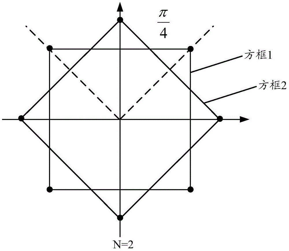
[0104] During downlink transmission, terminal 1 and terminal 2 occupy 3 data layers in total, and they reach any terminal through the same channel. The weight of each row of the 3-layer data of the encoding matrix is ​​2, that is, the number of phase rotations is N=2, and the modulation The constellation rotation factor matrix is:

[0105]

[0106] During uplink transmission, the data of terminal 1 and terminal 2 go through different channels, and the phase rotation is only implemented on the data of each layer in one terminal. One data layer occupied by terminal 1, the row weight of each row is 1, that is, the nu...

example 3

[0108] Example 3. Use Realize three-terminal transmission.

[0109] The encoding matrix is:

[0110]

[0111] The encoding matrix given in the above formula allocates three terminals, where the first column in the encoding matrix corresponds to the data layer of terminal 1, the second column corresponds to the data layer of terminal 2, and the third column corresponds to the data layer of terminal 3.

[0112] During downlink transmission, terminal 1, terminal 2, and terminal 3 occupy three data layers in total, and they go through the same channel to reach any terminal. The weight of each row of the three layers of data in the encoding matrix is ​​2, that is, the number of phase rotations N= 2. The modulation constellation rotation factor matrix is:

[0113]

[0114] During uplink transmission, the data of terminal 1, terminal 2, and terminal 3 go through different channels, and phase rotation is only implemented on the data of each layer in one terminal. Terminal 1 ...


PUM


Abstract

The embodiment of the invention relates to the technical field of wireless communication, and especially relates to a data transmission method, a receiving signal detection method and device, and a data transmission sending device. The methods and the devices are used for solving the problem that in the prior art, under a scene that each column of a coding matrix of PDMA (Pattern Division Multiple Access) corresponds to a layer of data streams, overlap occurs in multiple layers of data modulation symbols when detection is carried out at a receiving end, so that signal detection is influenced is solved. According to the embodiment of the method and the device, each layer of data modulation symbols obtained by modulating original modulation constellation graphs are adjusted according to modulation constellation twiddle factors corresponding to each layer of data modulation symbols, so that the modulation constellation graphs corresponding to each layer of data modulation symbols are not overlapped; the problem that under the scene that each column of the coding matrix of PDMA (Pattern Division Multiple Access) corresponds to one layer of data streams, overlap occurs in multiple layers of data modulation symbols, so that signal detection is influenced is avoided; and the system performance is further improved.

Description

technical field [0001] The invention relates to the technical field of wireless communication, in particular to a method and device for data transmission and received signal detection. Background technique [0002] The OFDMA (Orthogonal Frequency Division Multiple Access) access method used in the traditional LTE (Long Term Evolution, long-term evolution) system is designed based on the basic idea of ​​orthogonal transmission. The transmission and reception are simple and easy to implement, and the performance Can also be guaranteed. However, with the rapid development of mobile Internet services and Internet of Things business applications, non-orthogonal multiple access technology has greater advantages in improving system capacity, reducing delay, and supporting more terminals, and is likely to be adopted by 5G mobile communications. used by the system. Non-orthogonal multiple access technology transmits by superimposing information of different terminals on the same tr...

Claims


Application Information

Patent Timeline
IPC IPC(8): H04L5/00H04L27/34
CPCH04L5/0005H04L5/0007H04L27/04H04L27/20
Inventor 康绍莉任斌刘昊宋扬
Owner DATANG MOBILE COMM EQUIP CO LTD
Why Eureka
Try Eureka