Wireless charging device

A wireless charging and medical device technology, applied in circuit devices, battery circuit devices, current collectors, etc., can solve problems such as disadvantages and prolong fast charging time, and achieve the effects of reducing heat flow, lowering temperature, and good heat dissipation

Inactive Publication Date: 2016-11-23
SCENERAY
View PDF4 Cites 4 Cited by
  • Summary
  • Abstract
  • Description
  • Claims
  • Application Information

AI Technical Summary

Problems solved by technology

But it's not good for extending the fast charging time

Method used


Image

  • Wireless charging device
  • Wireless charging device

Examples


no. 1 example

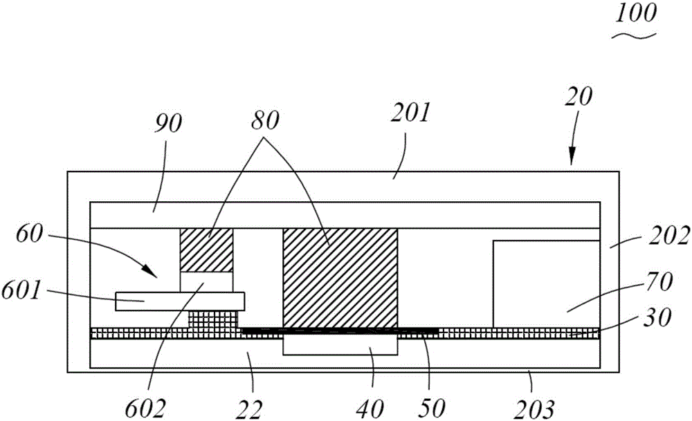
[0021] Such as figure 1 As shown, the preferred first embodiment of the wireless charging device of the present invention, the wireless charging device 100 includes a housing 20, a charging and heating component arranged in the housing 20, wherein the housing 20 has a bottom 203 close to the skin and an opposite top 201, the top The side 202 of the housing 20 is formed between the bottom 201 and the bottom 203 . The charging heating component is arranged near the bottom 203 . Specifically, a bracket 30 is provided inside the housing 20, and the bracket 30 is arranged near the bottom 203 and has an air gap 22 between it and the bottom 203. The charging heating component is supported on the bracket 30, so that the charging heating component and the bottom 203 are There is an air gap 22 . Due to the extremely low thermal conductivity of air, setting the air gap 22 can greatly reduce the transfer of heat generated by the charging heating component to the bottom 203 of the housin...


PUM


Abstract

The invention discloses a wireless charging device. The wireless charging device comprises a housing and a charging heating assembly, wherein the charging heating assembly is arranged in the housing and is used for charging a medical device implanted into a body, the housing is provided with a bottom which is close to skin and an opposite top, the charging heating assembly is close to the bottom, and an air gap is formed between the charging heating assembly and the bottom. The air gap is formed between the charging heating assembly and the bottom of the housing, so that a good heat dissipation effect can be achieved, and the temperature of one side, which is close to a human body, of the wireless charging device is reduced.

Description

technical field [0001] The invention relates to a wireless charging device, in particular to a wireless charging device for charging a rechargeable implantable medical device that can be implanted into a human body. Background technique [0002] Implantable medical devices come in a wide variety and range of applications, such as cardiac pacemakers and spinal cord stimulators, implantable neurostimulators, and more. Most of the existing implantable medical products on the market are powered by lithium primary batteries with high energy density, and most of them have a short lifespan. In recent years, with the development of wireless technology and lithium rechargeable battery technology, the development of rechargeable implantable medical devices with longer lifespan has become the mainstream trend of future development. [0003] The implantable medical device is implanted in the patient's body, and there is skin and other tissue isolation between the external charging devi...

Claims


Application Information

Patent Timeline
Patent Type & Authority Applications(China)
IPC IPC(8): H02J7/00H02J50/10H05K7/20
CPCH02J7/025H05K7/20472H05K7/20481
Inventor 王畅
Owner SCENERAY
Why Eureka
Try Eureka