Two-way retractable cable tray

A technology for cable trays and trays, which is applied to electrical components and other directions, can solve the problems of limited adjustment range, high cost and large amount of expansion and contraction of chain trays.

Active Publication Date: 2018-08-28
鞍山鸿维电力设备有限公司
View PDF5 Cites 0 Cited by
  • Summary
  • Abstract
  • Description
  • Claims
  • Application Information

AI Technical Summary

Problems solved by technology

[0004] 1. Since the length of each section of the bridge box of the current bridge is relatively long, the amount of expansion and contraction required between the bridge boxes is also relatively large. Although the cable expansion device can be used to lay the expansion and contraction requirements, the cost is relatively expensive and cannot be widely used. use
[0005] 2. The use of chain bridges can also achieve the purpose of telescopic adjustment of a certain length of cable, but the adjustment range of chain bridges is very limited, the general adjustment amount is about 300mm, and the adjustment amount between the bridge boxes of the bridge is about 800mm , so the chain bridge cannot be applied to such a sea-crossing bridge that requires a very large adjustment range

Method used


Image

  • Two-way retractable cable tray
  • Two-way retractable cable tray
  • Two-way retractable cable tray

Examples


Embodiment Construction

[0026] The specific implementation manner of the present invention will be further described below in conjunction with the accompanying drawings.

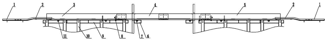
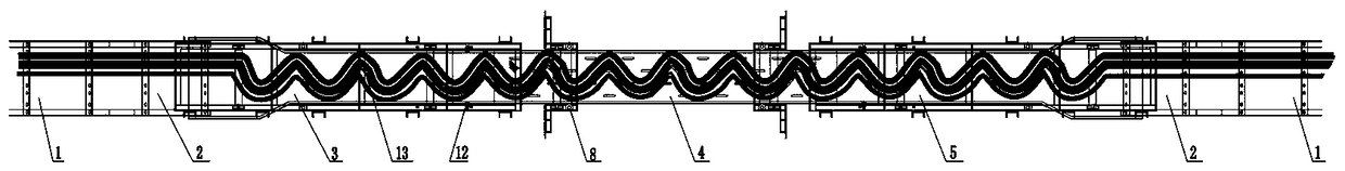
[0027] like figure 1 , 2 As shown in and 3, a bidirectional telescopic cable bridge of the present invention includes a telescopic bridge group arranged between two bridge box girders 1, and is characterized in that said telescopic bridge group includes Two Z-shaped cable bridges 2 fixedly connected, the telescopic bridge beam A3 arranged between the two Z-shaped cable bridges 2, the telescopic bridge beam B4 fixedly connected with the telescopic bridge beam A3, and the telescopic bridge beam B4 fixed The connected telescopic bridge girder C5 is respectively arranged on the supporting mechanism I at the lower part of the telescopic bridge girder A3 and the telescopic bridge girder C5, and the supporting mechanism II under the two ends of the telescopic bridge girder B4 is respectively arranged on the telescopic bridge girder A3 a...


PUM


Abstract

The invention belongs to the technical field of cable expansion and contraction, and particularly relates to a bidirectional telescopic cable bridge. The bidirectional telescopic cable bridge comprises a telescopic bridge group arranged between two bridge box beams, and is characterized in that the telescopic bridge group comprises two Z-shaped cable bridges, a telescopic bridge beam A arranged between the two Z-shaped cable bridges, a telescopic bridge beam B, a telescopic bridge beam C, supporting mechanisms I respectively arranged at lower parts of the telescopic bridge beam A and the telescopic bridge beam C, supporting mechanisms II respectively arranged under two ends of the telescopic bridge beam B, and limit rolls respectively arranged at end heads of the telescopic bridge beam A and the telescopic bridge beam C; a cable is fixed on the two Z-shaped cable bridges, the telescopic bridge beam A and the telescopic bridge beam C respectively and is put on the telescopic bridge beam B to form an S shape. The bidirectional telescopic cable bridge provided by the invention is specially arranged between two bridge boxes on a bridge pier, and effectively prevents the cable from being pulled apart or damaged by extrusion according to the characteristics of expansion, contraction and displacement of the adjacent two bridge boxes, so that the cable continuously supplies power.

Description

technical field [0001] The invention belongs to the technical field of cable telescopic, in particular to a bidirectional telescopic cable bridge. Background technique [0002] With the rapid development of the economy, the connection between the offshore islands and the mainland and between the bays is getting closer and closer. Therefore, the birth of the cross-sea bridge not only solves the problems of power supply, communication, and water supply on the islands, but also solves the problems of personnel exchanges and cargo transportation. problem, can be said to serve multiple purposes. Compared with laying expensive submarine cables, conventional cables are laid on the bridge, and the cables are laid inside the bridge, which is convenient for inspection and maintenance, which not only improves the operation reliability of the cables, but also has high economic efficiency . However, due to the influence of dynamic loads such as temperature changes, vehicle traffic, win...

Claims


Application Information

Patent Timeline
Patent Type & Authority Patents(China)
IPC IPC(8): H02G3/04
CPCH02G3/04
Inventor 许斌李宾徐超博杨正武李云峰袁世杰苏梁
Owner 鞍山鸿维电力设备有限公司
Why Eureka
Try Eureka