
Continuous power supply device

A technology of continuous power supply and power device, applied in circuits, electrical components, sensors, etc., can solve the problems of wasting labor, difficult to achieve continuous power supply, etc., and achieve the effect of stable structure

Active Publication Date: 2016-06-29
NINGBO DAHONGYING UNIV
View PDF12 Cites 5 Cited by
  • Summary
  • Abstract
  • Description
  • Claims
  • Application Information

AI Technical Summary

Problems solved by technology

However, in the current technology, in order to make the monitoring terminal move along the guide rail bracket to every corner of the farm for monitoring, the power device of the infrared real-time monitoring system needs power support, and the current method that can be used is mainly a battery, which needs to be replaced from time to time, which is wasteful. Labor force, and it is difficult to achieve the function of continuous power supply

Method used


Image

  • Continuous power supply device
  • Continuous power supply device
  • Continuous power supply device

Examples


Embodiment Construction

[0026] In order to make the technical means, creative features, objectives and effects of the present invention easy to understand, the following embodiments are combined with Figure 1 to 5 The continuous power supply device provided by the present invention is specifically explained.

[0027] Hereinafter, embodiments of the present invention will be described with reference to the drawings. In the embodiment, the same configuration is used for the same reference numeral and the description is omitted.

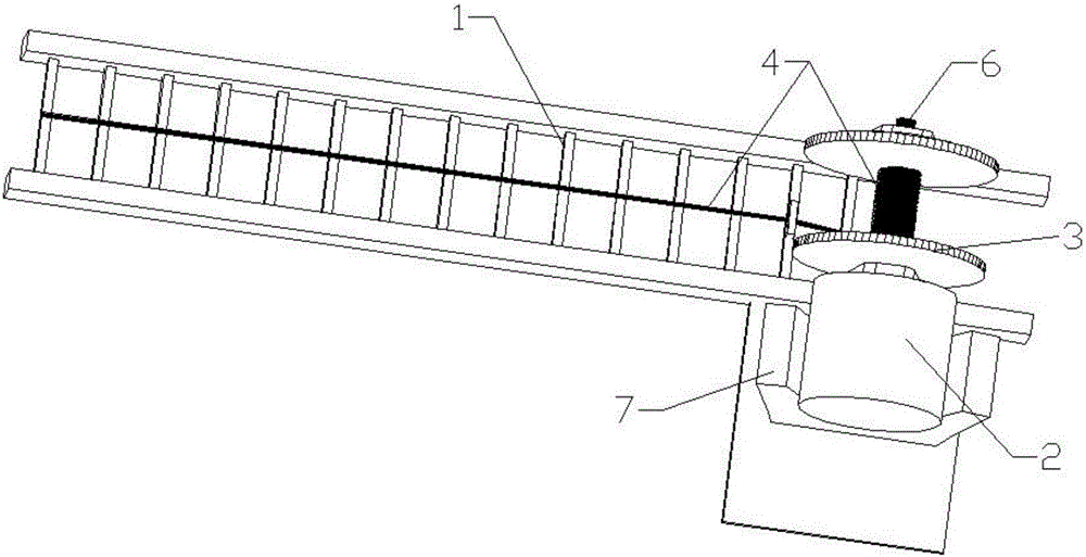
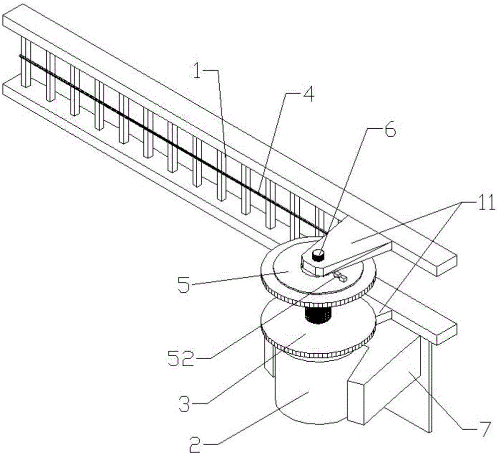
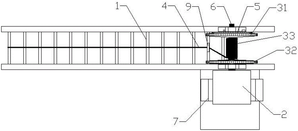
[0028] figure 1 Is an elevation view of the continuous power supply device in the embodiment of the present invention, figure 2 Is another perspective view of the continuous power supply device in the embodiment of the present invention, image 3 Is a top view of the continuous power supply device in the embodiment of the present invention, Figure 4 Is a schematic half-sectional plan view of the conductive wheel of the continuous power supply device in the embodiment of the prese...


PUM


Abstract

The invention discloses a continuous power supply device which is installed on a track support of an infrared real-time monitoring system and used for continuously providing power for a power device of a monitoring terminal. The continuous power supply device comprises a motor, a winding coil and a conductive wheel disc, wherein the motor is fixedly installed on the track support, the winding coil is installed on a motor shaft of the motor in a sleeving mode and is composed of a left turntable, a right turntable and a winding shaft fixedly connected with the left turntable and the right turntable, and the winding shaft is externally wound with a conductive cable. The conductive wheel disc is fixedly arranged on the track support and is opposite to the left turntable, two annular grooves are formed in the side facing the left turntable and are filled with a conductive material, and positive and negative pole contactor seats are arranged on the other side. Two notches opposite to the annular grooves are formed in the side, facing the conductive wheel disc, of the left turntable and are filled with a conductive material, positive and negative contactors are arranged on the other side, and the other end of the conductive cable is electrically connected with the positive and negative pole input ends of a power supply of the power device. By the adoption of the technical scheme, the continuous power supply device is easy to achieve and can keep a continuous power supply state of the power device of the monitoring terminal.

Description

Technical field [0001] The invention relates to the technical field of infrared real-time monitoring system equipment, in particular to a continuous power supply device. Background technique [0002] With the rise of scientific breeding concepts, livestock farms such as chickens, ducks, cattle, sheep, and pigs pay more and more attention to the concept of disease infection control and real-time monitoring. Animals usually change their body temperature when diseases occur. Infrared monitoring is usually used. The imaging processing method can determine the body temperature and disease status of a single animal. However, since infrared monitoring is usually located at only one point, the area of ​​the breeding farm is relatively large. It is necessary for the infrared real-time monitoring system to have a guide rail bracket so that the monitoring terminal can move along the guide rail bracket, so as to realize the monitoring of the livestock in every corner of the farm. Perform in...

Claims


Application Information

Patent Timeline
IPC IPC(8): G06Q50/02A61B5/01B65H75/38H01R35/00
CPCA61B5/01B65H75/38B65H2701/34G06Q50/02H01R35/00
Inventor 田思李永平章晓敏
Owner NINGBO DAHONGYING UNIV
Learn More