
Anti-sideways supporting wheel device

A technology of anti-deflection wheels and support wheels, applied in the direction of processing discharged materials, furnaces, lighting and heating equipment, etc., can solve the problems of increased wear, poor speed, easy damage, etc., to ensure normal operation and reduce friction Effect

Active Publication Date: 2018-08-07
NANJING KISEN INT ENG
View PDF9 Cites 0 Cited by
  • Summary
  • Abstract
  • Description
  • Claims
  • Application Information

AI Technical Summary

Problems solved by technology

However, this device has a defect, which makes it prone to damage during work; the specific reason is: in the design, it is assumed that the bearing surface of the T-shaped guide rail and the supporting roller device is in a pure rolling state when the in-line cooler is working, and there is no The speed difference, so theoretically there is no friction, which can ensure that the service life meets the design requirements; but in actual work, there is a speed difference between the two sides of the T-shaped guide rail and the two sides of the groove, which makes the T-shaped guide rail occur. Side deflection; when the side of the guide rail is in contact with the side of the groove, the relative movement of the two contact surfaces will lead to increased wear, which will lead to the anti-side deflection limit function of the T-shaped guide rail and the groove with the supporting roller device for a long time Weakening, worsening the working condition of the in-line cooler, and causing hidden dangers to the normal operation of the in-line cooler

Method used


Image

  • Anti-sideways supporting wheel device

Examples


Embodiment Construction

[0011] In order to make the object, technical solution and advantages of the present invention clearer, the present invention will be further described in detail below in conjunction with specific implementation methods and accompanying drawings. Here, the exemplary embodiments and descriptions of the present invention are used to explain the present invention, but not to limit the present invention.

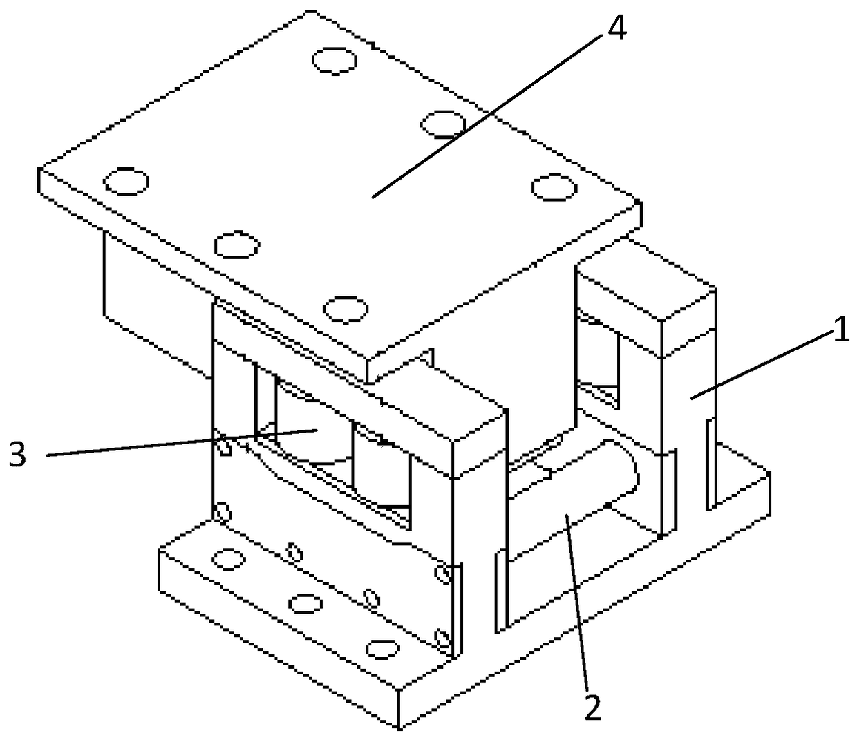
[0012] As shown in the figure, the anti-sideways support roller device of the present invention is composed of a frame 1, a support roller 2, an anti-deflection wheel 3 and a T-shaped guide rail 4; the frame 1 is a U-shaped groove with an opening at the top; the support roller 2 It forms a rotational connection with both sides of the inner bottom of the frame 1; square through holes are provided on the two side walls of the frame 1, and anti-deflection wheels 3 are installed in the through holes; The circumferential surface forms the contact connection.

[0013] Further, in ord...


PUM


Abstract

The invention relates to a supporting wheel device, especially a side-deflection-proof supporting wheel device, which is composed of a frame, a supporting supporting wheel, an anti-deflection wheel and a T-shaped guide rail; The deflection wheel makes the T-shaped guide rail contact with the side anti-deflection wheel when the external force or its own deformation shifts to the side, preventing the T-shaped guide rail from further lateral deflection, and eliminating the vertical deflection of the T-shaped guide rail during the operation of the inline cooler. There is a speed difference between the two sides of the straight section and the two sides of the groove of the supporting roller, which reduces friction and ensures the normal operation of the in-line cooler.

Description

technical field [0001] The invention relates to a supporting wheel device, in particular to a side deviation preventing supporting wheel device. Background technique [0002] The working straightness requirements of the inline cooler are very high; all inline cooler manufacturers have taken measures to strictly limit the left and right lateral deflection of the cooler when it is running, so as to ensure its linear motion. [0003] In order to prevent the left and right side deviation of the in-line cooler, the traditional method is to combine the groove with the supporting roller device and the T-shaped guide rail plate, and use the cooperation between the groove with the supporting roller device and the T-shaped guide rail plate to prevent each The lateral deviation of the column; its working principle is: the raised part of the T-shaped guide rail plate is embedded in the groove with the supporting roller device, and the two sides of the groove are used to limit the left a...

Claims


Application Information

Patent Timeline
Patent Type & Authority Patents(China)
IPC IPC(8): F27D15/02
Inventor 李帅波徐靖李立华陈新平胡斌
Owner NANJING KISEN INT ENG
Learn More