Rotating limiting support for thermal pipe and rotating limiting method of support

A technology of rotation limit and thermal pipeline, which is applied in the field of rotation limit support for thermal pipeline and rotation limit support for thermal pipeline, which can solve the problems of small thrust

Inactive Publication Date: 2016-11-23
CENT SOUTHERN CHINA ELECTRIC POWER DESIGN INST CHINA POWER ENG CONSULTING GROUP CORP
View PDF7 Cites 3 Cited by
  • Summary
  • Abstract
  • Description
  • Claims
  • Application Information

AI Technical Summary

Problems solved by technology

[0004] In engineering design, sometimes it is necessary to limit the linear displacement of the fulcrum in three directions, but not to limit the angular displacement of the pipeline on a certain plane; The support needs to limit the linear displacement in three directions at the fulcrum, but not limit its angular displacement, so as to realize the use of the angular displacement of the pipeline itself to compensate the elastic deformation of the pipeline and achieve the effect of releasing the thermal stress of the pipeline; Under the action of stress, the thrust of the intermediate support will be very small; however, there is no suitable support and hanger to choose from the existing support and hanger forms.
[0005] The conventional fixed support, the pipe clamp and the pipe, the base and the supporting foundation are all welded and fixed, and the linear displacement and angular displacement at the fulcrum are all locked; the current limit device can only limit the movement in one direction or two directions. The fixed bracket limits the linear displacement and angular displacement in all directions; in the form of the existing support and hanger, it is still impossible to limit the angular displacement under the premise of restricting the linear displacement in the three directions of the fulcrum position.

Method used


Image

  • Rotating limiting support for thermal pipe and rotating limiting method of support
  • Rotating limiting support for thermal pipe and rotating limiting method of support
  • Rotating limiting support for thermal pipe and rotating limiting method of support

Examples


Embodiment Construction

[0030] The implementation of the present invention will be described in detail below in conjunction with the accompanying drawings, but they do not constitute a limitation to the present invention, and are only examples. At the same time, the advantages of the present invention are clearer and easier to understand through the description.

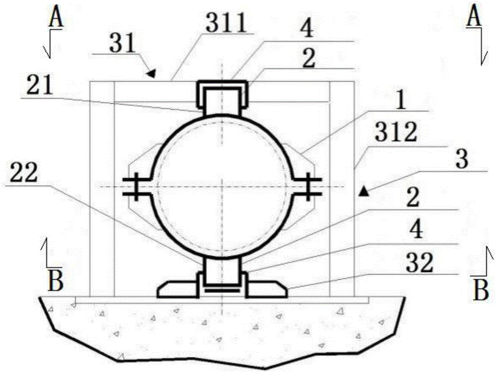
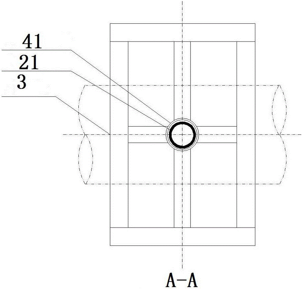
[0031] Referring to the accompanying drawings, it can be seen that: a rotating limit support for thermal pipelines, including a pipe clamp 1, a rotating shaft 2, and a support system 3; the support system 3 includes a support frame 31 and a support plate 32; the support frame 31 includes a lateral Support frame 311, longitudinal support frame 312; the rotating shaft 2 includes an upper rotating shaft 21 and a lower rotating shaft 22, the lower end of the upper rotating shaft 21 is welded to the upper end of the pipeline, and the upper end of the lower rotating shaft 22 is welded to the lower end of the pipeline There is a rotating shaft gro...


PUM


Abstract

The invention discloses a rotating limiting support for a thermal pipe. The support comprises a pipe clamp, rotating shafts and a supporting system, wherein the supporting system comprises a supporting frame and a supporting plate; the supporting frame comprises a transverse supporting frame and longitudinal supporting frames; the rotating shafts comprise an upper rotating shaft and a lower rotating shaft, the lower end of the upper rotating shaft is welded at the upper end of the pipe, and the upper end of the lower rotating shaft is welded at the lower end of the pipe; rotating shaft grooves are located in the supporting system; and the rotating shafts are sleeved with the rotating shaft grooves. The support overcome defects that only linear displacement in one or two directions can be limited and angular displacement is limited on the premise that the linear displacement of the position of a supporting point is limited in the prior art are overcome; and the rotating limiting support has the advantages that the rotating shafts are increased on the pipe clamp, and limiting supporting is designed, so that the linear displacement of the pipe in a heated state is limited, the angular displacement is allowed on a certain plane, and partial swelling stress is released. The invention further discloses a rotating limiting method of the rotating limiting support for the thermal pipe.

Description

technical field [0001] The invention relates to the field of heat pipe supports, more specifically, it is a rotation limiting support for heat pipes. The invention also relates to a rotation limiting method of a rotating limiting support for a thermal pipeline. Background technique [0002] At present, in the thermal pipeline design, the pipeline has six degrees of freedom in the directions of X, Y, Z, RX, RY, and RZ at the supporting point. According to the needs of pipeline design, different supports and hangers are selected to constrain one of them. degrees of freedom or certain degrees of freedom to achieve the purpose of safe and economical operation of thermal pipelines; currently widely used types of supports and hangers (or called restraint forms) are: spring support and hanger, rigid hanger, sliding support , Rolling bracket, guide bracket, limit device, fixed bracket, vibration reduction device and damping device, etc. [0003] Among the above types of supports a...

Claims


Application Information

Patent Timeline
IPC IPC(8): F16L3/11F16L3/16
CPCF16L3/11F16L3/16
Inventor 王坚舒涛龙仕军王汉强周天情陈琪
Owner CENT SOUTHERN CHINA ELECTRIC POWER DESIGN INST CHINA POWER ENG CONSULTING GROUP CORP
Why Eureka
Try Eureka