
Efficient liquid distribution pipe

A technology of liquid distribution pipes and distribution pipes, applied in chemical/physical/physical chemical processes, chemical instruments and methods, chemical/physical processes, etc., can solve problems such as insufficient vapor-liquid contact, poor mass and heat transfer effects, etc. Achieve increased area, facilitate mass transfer and heat transfer, and improve the effect of mass and heat transfer

Inactive Publication Date: 2016-11-23
合肥天沃能源科技有限公司
View PDF0 Cites 0 Cited by
  • Summary
  • Abstract
  • Description
  • Claims
  • Application Information

AI Technical Summary

Problems solved by technology

[0002] At present, in the petrochemical field, there are many liquid process media that need to be distributed to meet the production requirements of vapor-liquid contact. The traditional distribution methods are: overflow type , Spray type, due to uneven distribution, the vapor-liquid contact is insufficient, resulting in poor mass and heat transfer effect

Method used


Image

  • Efficient liquid distribution pipe
  • Efficient liquid distribution pipe

Examples


Embodiment Construction

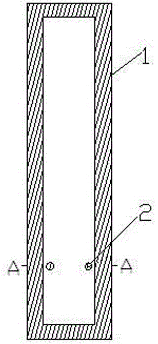
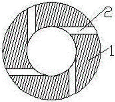
[0008] exist Figure 1-2 Among them, it includes a distribution pipe 1, and four round holes 2 with a diameter of 2.5mm are drilled equidistantly on the same horizontal line in the lower part of the pipe wall of the distribution pipe 1. The round holes 2 pass from the outside of the pipe to the inside of the pipe, so that the liquid is spiral Into the tube, and can be distributed along the inner wall of the tube in a film shape, the direction of the round hole 2 is tangent to the distribution tube 1, and the four round holes 2 are all at the same elevation.


PUM

PropertyMeasurementUnit
Diameteraaaaaaaaaa

Abstract

A high-efficiency liquid distribution pipe relates to a liquid distribution pipe. It includes a distribution pipe. Four circular holes with a diameter of 2.5mm are drilled equidistantly on the same horizontal line in the lower section of the distribution pipe. The circular holes lead from the outside of the pipe to the inside of the pipe. The holes are all at the same level. The practical technology achieves the precise distribution of the liquid by changing the flow direction of the liquid entering the pipe, increases the contact area of ​​the vapor and liquid, and is more conducive to the mass transfer and heat transfer in the process.

Description

technical field [0001] The invention relates to a high-efficiency liquid distribution pipe. Background technique [0002] At present, in the field of petrochemical industry, there are many liquid process media that need to be distributed to meet the production requirements of vapor-liquid contact. The traditional distribution methods include: overflow type, spray type, and insufficient vapor-liquid contact due to uneven distribution. The mass and heat transfer effect is poor. Contents of the invention [0003] Precisely distribute the liquid in the process of process production to improve the mass transfer and heat transfer effect required by the process. [0004] The technical solution adopted by the present invention to solve the technical problem is: it includes a distribution pipe, and four round holes with a diameter of 2.5 mm are drilled equidistantly on the same horizontal line in the lower section of the distribution pipe, and the round holes pass from the outside...

Claims


Application Information

Patent Timeline
IPC IPC(8): B01J19/32
CPCB01J19/32B01J2219/32279B01J2219/332
Inventor 魏芳芳
Owner 合肥天沃能源科技有限公司
Learn More