
Gas turbine

A gas turbine and turbine technology, which is applied to gas turbine devices, liquid fuel engines, combustion chambers, etc., can solve problems such as high heat load, and achieve the effect of reducing load capacity requirements and reducing costs

Inactive Publication Date: 2016-11-16
SIEMENS AG
View PDF6 Cites 4 Cited by
  • Summary
  • Abstract
  • Description
  • Claims
  • Application Information

AI Technical Summary

Problems solved by technology

[0010] However, with these solutions known from the prior art, due to the high temperatures (up to 1400° C.) occurring in the combustion chamber of a gas turbine, the material delimiting the inner walls of the combustion chamber is subjected to high thermal loads

Method used


Image

  • Gas turbine
  • Gas turbine
  • Gas turbine

Examples


Embodiment Construction

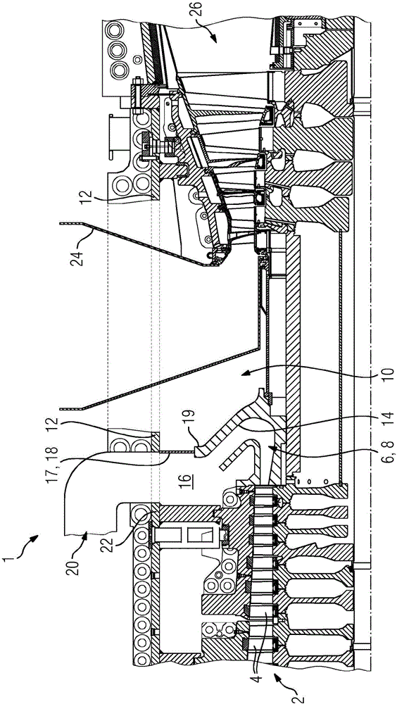
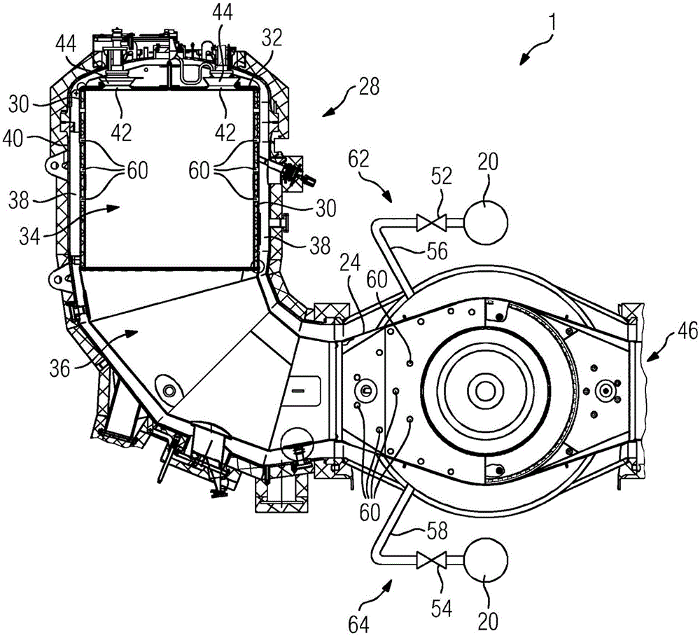
[0037] figure 1 A partial schematic view showing details of the gas turbine 1 . The gas turbine 1 comprises a compressor 2 having a compression chamber 4 which leads to an outlet 8 designed as an outlet diffuser 6 . In this case, the outlet diffuser 6 has a manifold 14 of U-shaped cross-section continuing away from the interior space 10 of the intermediate housing 12 . The plenum 16 is connected to the compressor 2 via the outlet diffuser 6 and is separated from the interior 10 of the intermediate housing 12 by a wall 17 . In this case, the peripheral wall 17 consists of a peripheral partition 18 which extends radially from the outer edge 19 of the manifold 14 to the intermediate casing 12 . From this plenum 16 a discharge line 20 is led through a front casing 22 connected to the intermediate casing 12 and surrounding the compressor 2 and connected to a heat exchanger (in a manner not shown in more detail in the figures).

[0038] The inner casing 24 is guided through the i...


PUM


Abstract

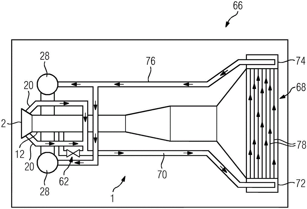
The invention relates to a gas turbine (1) which comprises a compressor (2), a central housing (12), at least one combustion chamber (28), an expansion turbine (26), and a heat exchanger (68). Each combustion chamber (28) is fluidically connected to the expansion turbine (26) via an inner housing (24) which is guided through the interior (10) of the central housing (12). The compressor (2) is fluidically separated from the interior (10) of the central housing (12) by an annular collection chamber (16) which is connected to an outlet (8) of the compressor (2) and which has a number of discharge lines (20) which are connected to the cold side (72) of the heat exchanger (68) during operation. Each combustion chamber is designed as a silo combustion chamber (22), and each silo combustion chamber (28) has an inner wall (30), which delimits a combustion chamber (34), and an outer wall (40), and the outer wall (40) surrounds the inner wall (30), thereby forming a cavity (38). The inner wall (30) transitions into the inner housing (24), and the cavity (38) transitions into the interior (10) of the central housing (12).

Description

technical field [0001] The invention relates to a gas turbine comprising a compressor, an intermediate casing, at least one combustion chamber and an expansion turbine, wherein the or each combustion chamber is fluidly connected to the expansion turbine via an inner casing which is guided through the intermediate casing interior space. Background technique [0002] In a gas turbine, the heat of combustion of fuel is converted into mechanical work. The thermodynamic cycle describing this transition approximately fits the Joule cycle. [0003] In that case, first, the compressor chamber compresses an oxygen-containing working gas, which is generally air in practice, during which the temperature of the gas changes from the starting temperature T 1 heat to T 2 , and the pressure increases. In the second step, as the temperature rises further to T 3 , by igniting the mixed fuel to supply heat to the working gas in the combustion chamber at a constant pressure. The compresse...

Claims


Application Information

Patent Timeline
Patent Type & Authority Applications(China)
IPC IPC(8): F02C3/14F02C7/08
CPCF02C3/14F02C7/08F23R2900/03342F05D2230/80Y02E20/16F01D9/023F01D25/24F02C3/04F02C3/145F02C7/10F02C7/18F02C9/18F02C9/20F04D29/541F05D2220/32F05D2240/35F23R3/002F23R3/60
Inventor M·维尔克
Owner SIEMENS AG
Learn More