Plasma generator applied to auxiliary ignition in shock tube

A technology of plasma and shock tube, applied in the field of plasma generation device, to achieve the effect of maintaining stability

Inactive Publication Date: 2016-11-16
PLA PEOPLES LIBERATION ARMY OF CHINA STRATEGIC SUPPORT FORCE AEROSPACE ENG UNIV
View PDF7 Cites 0 Cited by
  • Summary
  • Abstract
  • Description
  • Claims
  • Application Information

AI Technical Summary

Problems solved by technology

[0010] (3) The discharge will corrode some parts of the plasma generating device, therefore, some parts of the plasma generating device need to be replaceable

Method used


Image

  • Plasma generator applied to auxiliary ignition in shock tube
  • Plasma generator applied to auxiliary ignition in shock tube
  • Plasma generator applied to auxiliary ignition in shock tube

Examples


Embodiment Construction

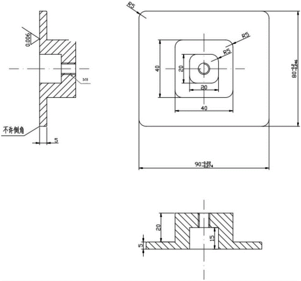
[0028] Such as figure 1 As shown, the discharge unit is composed of a base (3), a pressure block (4), a plug (5) and a copper bolt (6). There is a gap in the fit between the base (3) and the plug (5), and the purpose is to reserve a copper mesh to pass through. The pressure block (4) and the copper bolt (6) are connected by M8 threads. The copper mesh is connected to the copper bolt in the cavity of the pressure block (4), and the copper bolt is welded with wires to connect to the external plasma power supply. Therefore, when the plasma power supply is turned on, the copper mesh in the discharge unit will pass through The dielectric layer and the shock tube body discharge.

[0029] Figure 2(a) shows the schematic structure of the plug. The material of the plug is polytetrafluoroethylene, and the plug is designed with notches for embedding the copper mesh. Since the discharge will have a corrosive effect on the PTFE insulation layer, the plug can be replaced after a period of u...


PUM


Abstract

The invention provides a plasma generator applied to ignition and combustion-supporting in a shock tube. The plasma generator comprises a discharge unit, a gland and a plasma power supply, wherein the discharge unit comprises a base, a press block, an end cap and a copper bolt; and a copper screen is embedded into the end cap and extends outside through a gap between the end cap and the base to wind and connect the copper bolt. The gland is designed into two parts, is mainly used for pressing the discharge unit to fix and seal the discharge unit and is connected with a shock tube body. The plasma power supply part comprises a host and a transformer; the host can adjust plasma discharge power; and the transformer takes charge of adjusting discharge peak voltage and a discharge frequency. The plasma generator is compact in structure, does not affect flowing of a shock wave after being installed, generates plasma in the shock tube and is used for researching auxiliary ignition and combustion supporting of the plasma, and can adapt to the experiment requirements of various working conditions; and the concentration of the plasma can be adjusted.

Description

Technical field [0001] The invention belongs to the technical field of combustion experiments, and is a plasma generating device used in a shock tube for studying plasma auxiliary ignition. Background technique [0002] When the flying speed of the aircraft reaches hypersonic speed, the combustion in the ramjet reaches a super-combustion state, which is called a scramjet. For scramjet engines, fuel flows through the combustion chamber at supersonic speed, and it is difficult for the fuel to achieve mixing, ignition and full release of chemical energy. Hydrocarbon fuel is the most widely used fuel for aviation aircraft. The fuel needs to complete ignition, flame propagation and flame stabilization in a very short time (on the order of milliseconds). The ignition delay time of hydrocarbon fuel is also on the order of milliseconds. Therefore, technical means must be used to shorten the ignition delay time of hydrocarbon fuel. [0003] Plasma is considered to be the most effective me...

Claims


Application Information

Patent Timeline
Patent Type & Authority Applications(China)
IPC IPC(8): H05H1/24
CPCH05H1/24
Inventor 金星赵文涛沈双晏徐庆尧王殿恺钟文丽
Owner PLA PEOPLES LIBERATION ARMY OF CHINA STRATEGIC SUPPORT FORCE AEROSPACE ENG UNIV
Why Eureka
Try Eureka