Rotary type fracture sand jet and multistage sand jetting and fracturing process

A rotary, sandblaster technology, applied in the fields of production fluids, wellbore/well components, earth-moving drilling, etc., can solve the problems of high construction cost, long operation period, shrinking inner diameter of pipe strings, etc., and shorten the construction operation time. , The effect of increasing construction reliability and improving service life

Active Publication Date: 2016-11-16
铁岭曲氏石油技术开发服务有限公司
View PDF6 Cites 2 Cited by
  • Summary
  • Abstract
  • Description
  • Claims
  • Application Information

AI Technical Summary

Problems solved by technology

[0004] 1. In the technology of ball throwing and sliding sleeve, the pipe string can only be constructed step by step, without targeted construction ability, and the inner diameter of the pipe string is gradually reduced, so it is impossible to realize large-displacement construction in multi-stage construction
[0005] 2. Although the process of running and opening the string to open the sliding sleeve can be constructed for a certain layer, there are problems such as repeated running of the process string during the construction of the cased well, long operation period and high construction cost.
[0006] 3. The weak electric induction opening sliding sleeve needs to be brought into the sensing cable or weak point sensor in the process of lowering the pipe string. During the construction process, due to the complex situation in the well, it is very easy to cause the sensor to fail or the sliding sleeve cannot be opened.

Method used


Image

  • Rotary type fracture sand jet and multistage sand jetting and fracturing process
  • Rotary type fracture sand jet and multistage sand jetting and fracturing process
  • Rotary type fracture sand jet and multistage sand jetting and fracturing process

Examples


Embodiment Construction

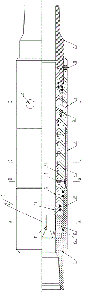
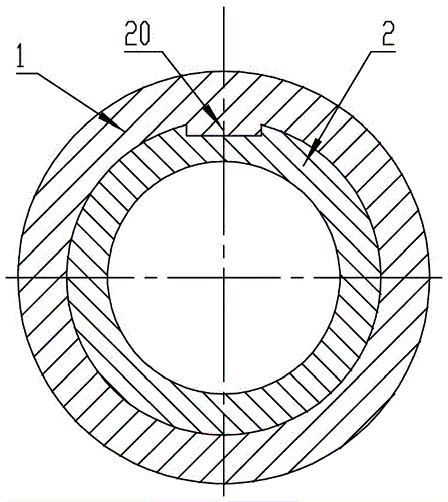
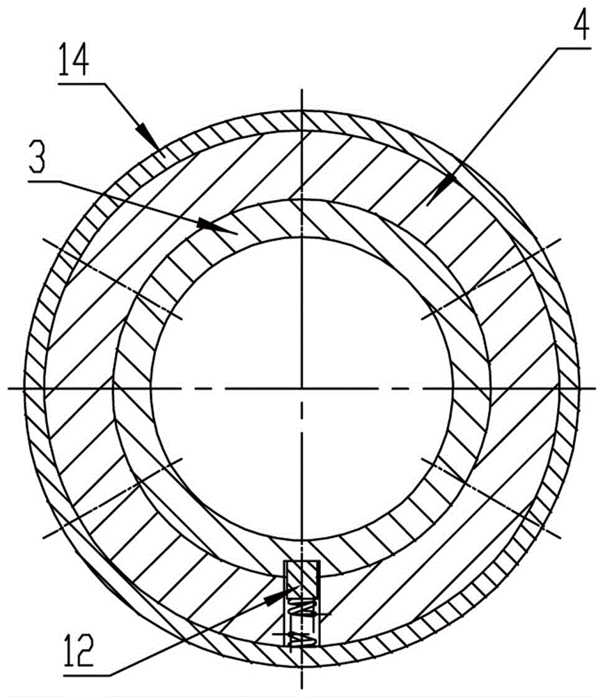
[0034] Such as Figure 1 to Figure 6 As shown, a rotary fracturing sand blaster, one end of the sand blaster main body 4 is sealed and connected with the upper joint 1, and the other end is sealed and connected with the lower joint 7, and the inner circumference of the sand blaster main body 4 is provided with a rotary sliding sleeve The inner core 3 is provided with several shear nail grooves 21 in the middle of the outer circumferential surface of the inner core 3 of the rotary sliding sleeve, and several spring-type telescopic shear nail combinations 12 are arranged on the main body 4 of the sand blaster, wherein the spring-type telescopic shear The nail assembly 12 is a spring-supported shear nail structure. When the inner core 3 of the rotary sliding sleeve rotates at a fixed angle, a spring-type telescopic shear nail assembly 12 falls into the corresponding shear nail groove 21; One end of the sliding sleeve inner core 3 close to the upper joint 1 is provided with a rota...


PUM


Abstract

The invention relates to a rotary type fracture sand jet and a multistage sand jetting and fracturing process. The rotary type fracture sand jet is structurally characterized in that an upper connector and a lower connector are connected with the two ends of the fracture sand jet; a rotary type slide sleeve inner core is arranged on the inner circumference of the fracture sand jet; a plurality of shear pin grooves are formed in the middle of the surface of the outer circumference of the rotary type slide sleeve inner core; a plurality of spring type extensible shear pin assemblies are arranged on a fracture sand jet body, and one spring type extensible shear pin assembly falls into the corresponding shear pin groove; a rotary control mechanism is arranged at the end, close to the upper connector, of the rotary type slide sleeve inner core; rotary sand jetting holes distributed evenly and circumferentially are formed in the end, close to the lower connector, of the rotary type slide sleeve inner core; outer sand jetting holes distributed evenly and circumferentially are formed in the fracture sand jet body; and the outer sand jetting holes correspond to the rotary sand jetting holes in position. A rotary opening type is adopted for the fracture sand jet. In the construction process, the opening process is stable and reliable, and construction can be conducted independently for a layer section; and after construction, a slide sleeve of the constructed layer section can be closed, and layered sand jetting management can be effectively conducted for the stratum.

Description

technical field [0001] The invention relates to a rotary fracturing sandblasting device and a multi-stage sandblasting fracturing process, which are used to realize large-displacement multi-stage layered reconstruction of vertical wells and horizontal wells inside casings, outside casings, and satisfy oil (gas) fields. The sand blaster required by the large-displacement fracturing reconstruction process. Background technique [0002] At present, the sliding sleeve sand blasters used in oil and gas field fracturing, acidizing, water injection and other construction processes all adopt the opening process of channel tools by throwing a ball to open the sliding sleeve, lowering the opening string to open the sliding sleeve, and weak electric induction to open the sliding sleeve. [0003] The above three opening processes have the following problems [0004] 1. In the technology of throwing balls to open the sliding sleeve, the pipe string can only be constructed step by step, ...

Claims


Application Information

Patent Timeline
Patent Type & Authority Applications(China)
IPC IPC(8): E21B43/26
CPCE21B43/26
Inventor 曲哲曲绍琨荣雷王兵元
Owner 铁岭曲氏石油技术开发服务有限公司
Why Eureka
Try Eureka