Multi-rotor unmanned aerial vehicle

A multi-rotor UAV, brushless motor technology, applied in the direction of rotorcraft, unmanned aerial vehicle, fuselage, etc., can solve the problems of inconvenient traffic conditions, difficult to pass, throwing material waste, etc., to improve accuracy and safety. The effect of utilizing efficiency, highlighting application value and improving work efficiency

Inactive Publication Date: 2016-11-16
四川克瑞斯航空科技有限公司
View PDF5 Cites 5 Cited by
  • Summary
  • Abstract
  • Description
  • Claims
  • Application Information

AI Technical Summary

Problems solved by technology

For example, at present, in important occasions such as celebrations, commercial promotions, and group activities, the operation methods for creating scenes such as flower petals, snowflakes, and promotional materials are still done manually or mechanically on the ground, which has poor sense of reality and requires many hands. , and other shortcomings
In the emergency response to disasters, for the trapped people who need help, due to the limitations of transportation devices, on-site disaster environment, traffic conditions and other factors, it is impossible to achieve the fastest response
For disasters such as high-rise building fires, earthquakes, and rock landslides, the traffic conditions are inconvenient or severely damaged, and the ground is difficult to pass even on foot, hindering the transportation and delivery of relief materials
For the existing air delivery method of relief supplies, on the one hand, it is inconvenient to dispatch the aircraft and consumes a lot of money. For throwing, it is difficult to accurately locate the throwing point, and there is a large waste of throwing materials, and the degree of utilization is low; for low-altitude helicopters, the operation is difficult and the risk is greater

Method used


Image

  • Multi-rotor unmanned aerial vehicle
  • Multi-rotor unmanned aerial vehicle
  • Multi-rotor unmanned aerial vehicle

Examples


Embodiment Construction

[0015] In order to make the object, technical solution and advantages of the present invention clearer, the present invention will be further described in detail below in conjunction with the accompanying drawings.

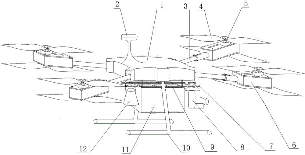
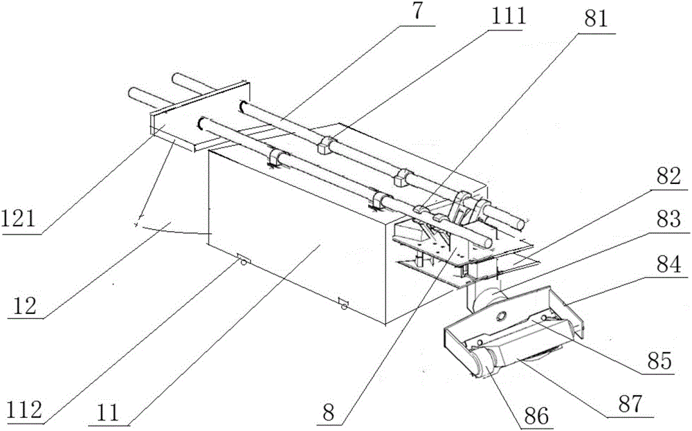
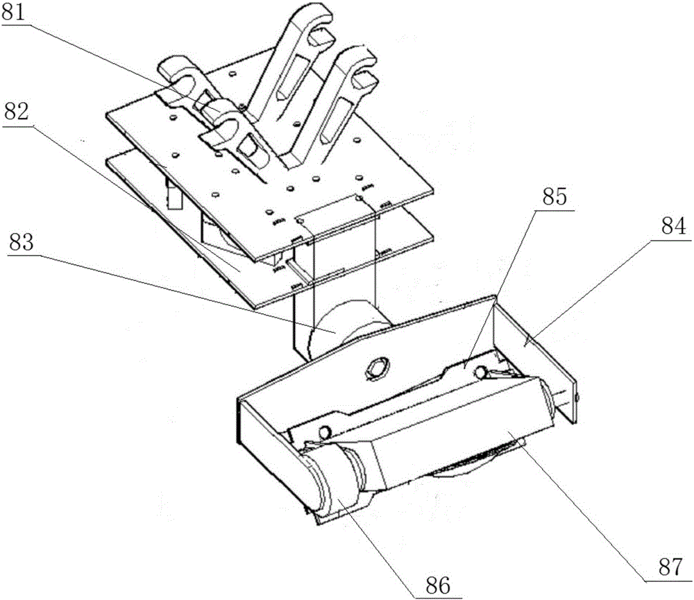
[0016] Such as figure 1 As shown, a kind of multi-rotor unmanned aerial vehicle provided by the present invention comprises center board 1, tripod 10, machine arm 3, motor base 6, motor 5, propeller 4 and antenna 2, and described tripod 10 is located at center board 1, the antenna 2 is arranged above the center plate 1, one end of the arm 3 is connected to the center plate 1 through a joint, and the other end is connected to the motor base 6, the motor 5 is installed on the motor base 6, and the propeller 4 is installed on the On the motor 5; the bottom of the center plate 1 is also provided with a suspension bracket 9, and two parallel mounting rods 7 are arranged on the suspension bracket 9; the camera mechanism 8 and the pod mechanism are sequentially mounted o...


PUM


Abstract

The invention discloses a multi-rotor unmanned aerial vehicle, which comprises a center plate, a foot stand, jib arms, motor bases, motors, screw propellers and an antenna. The foot stand is arranged under the center plate; the antenna is arranged above the center plate; one ends of the jib arms are connected with the center plate through joint parts; the other ends of the jib arms are connected with the motor bases; the motors are arranged on the motor bases; the screw propellers are arranged on the motors; a suspension frame is also arranged on the bottom part of the center plate; two parallel mounting rods are arranged on the suspension frame; and a camera mechanism, a nacelle mechanism and a loudspeaker are sequentially mounted on the mounting rods. The multi-rotor unmanned aerial vehicle provided by the invention applies a low-altitude flight platform of a small unmanned aerial vehicle, and is simple in structure, convenient to operate and control, and excellent in using effect, and the application field of the small unmanned aerial vehicle is widened.

Description

technical field [0001] The invention relates to the field of mechanical technology, in particular to a multi-purpose multi-rotor drone. Background technique [0002] With the rapid development of high-tech technologies such as automatic control technology and information technology, great progress has also taken place in UAV technology. In particular, low-altitude small and micro UAVs have the remarkable characteristics of short development cycle, low cost, low risk of use, and easy operation and learning. field. For example, at present, in important occasions such as celebrations, commercial promotions, and group activities, the operation methods for creating scenes such as flower petals, snowflakes, and promotional materials are still done manually or mechanically on the ground, which has poor sense of reality and requires many hands. , and other shortcomings. In the emergency response to disasters, for the trapped people who need help, due to the limitations of transpo...

Claims


Application Information

Patent Timeline
Patent Type & Authority Applications(China)
IPC IPC(8): B64C1/30B64C27/10B64D1/08B64D47/02B64D47/08
CPCB64C1/30B64C27/10B64D1/08B64D47/02B64D47/08B64U2101/00B64U10/10B64U2101/60B64U50/19B64U2101/30
Inventor 李振宇
Owner 四川克瑞斯航空科技有限公司
Why Eureka
Try Eureka