
Charging circuit and control method thereof

A technology of a charging circuit and a control method, which is applied to battery circuit devices, circuit devices, collectors, etc., can solve the problems of PFC positive and negative half-cycle power input asymmetry, positive and negative bus load asymmetry, negative bus no energy input, etc., Achieve the effects of reducing device costs, avoiding harmonic pollution, and reducing the step-down ratio

Active Publication Date: 2016-11-09
ZHANGZHOU KEHUA ELECTRIC TECH CO LTD
View PDF3 Cites 0 Cited by
  • Summary
  • Abstract
  • Description
  • Claims
  • Application Information

AI Technical Summary

Problems solved by technology

[0004] This topology has the following defects: If the BUCK charging circuit on either side is disconnected (circuit failure or battery abnormality, etc.), it will cause asymmetrical loads on the positive and negative bus bars, which will cause unbalanced positive and negative bus bars, resulting in PFC positive and negative half-cycle power input Asymmetry, causing harmonic pollution to the grid
[0006] This topology has the following defects: when the mains power is in the positive half cycle, the positive busbar is boosted to store energy continuously, and the negative busbar has no energy input. However, since the input of BUCK charging is the total voltage of the positive and negative busbars, the electrolysis of the negative busbar continues at this time. emit energy

Method used


Image

  • Charging circuit and control method thereof
  • Charging circuit and control method thereof
  • Charging circuit and control method thereof

Examples


Embodiment Construction

[0023] The present invention will be further described below in conjunction with the accompanying drawings and embodiments.

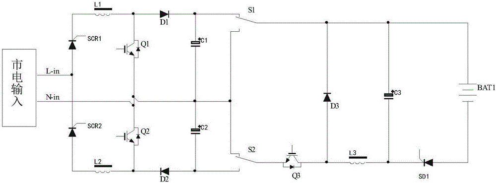
[0024] Such as image 3 As shown, a charging circuit, the circuit includes:

[0025] The anode of the first thyristor SCR1 is connected to the cathode of the second thyristor SCR2 and connected to the live wire of the mains input, the cathode of the first thyristor SCR1 is connected to the first end of the first inductor L1, and the other end of the first inductor L1 is connected to the first end of the first thyristor L1. The anode of the diode D1 is connected to one end of the first switching device Q1, and the cathode of the first diode D1 is connected to the anode of the first polarity capacitor C1 and the first branch selection end of the first selection unit S1,

[0026] The other end of the first switching device Q1, one end of the second switching device Q2, the negative pole of the first polarity capacitor C1, the positive pole of the second p...


PUM


Abstract

The invention provides a charging circuit and a control method thereof. The charging circuit only comprises a group of BUCK charging circuit, the number of the devices is small, and the cost of the devices is relatively low. The voltage input of a single bus is still used, and the states of a first selection unit S1 and a first selection unit S2 are controlled by the input according to whether the voltage of the commercial power is in the positive half cycle or the negative half cycle at present, so that whether a positive bus or a negative bus is accessed is determined, the BUCK step-down ratio is low, the stress of a first switch device Q1 is small, the efficiency is high, the electrolysis capacity of the bus does not need to be large, and the cost of the device is lowered. The technical scheme solves the problems in the prior art that the imbalance of positive and negative buses is caused by load dissymmetry of positive and negative buses and input imbalance of PFC positive and negative semi-cycle power is caused, so that the harmonic pollution caused to the power grid is avoided.

Description

technical field [0001] The invention relates to the field of power supplies, in particular to a charging circuit and a control method thereof. Background technique [0002] The uninterruptible power supply system has been widely used in various power supply occasions. When the mains power is abnormal or cut off, it can continue to supply power to the load, and can ensure the quality of power supply, so that the power supply to the load will not be affected, and can ensure the reliability of power supply to the load. sex. [0003] figure 1 Shown is the current commonly used charging topology, which has two sets of symmetrical BUCK charging circuits (or two sets of symmetrical flyback charging circuits), whose inputs are respectively connected to the positive bus and the negative bus. [0004] This topology has the following defects: If the BUCK charging circuit on either side is disconnected (circuit failure or battery abnormality, etc.), it will cause asymmetrical loads on...

Claims


Application Information

Patent Timeline
Patent Type & Authority Applications(China)
IPC IPC(8): H02J7/06H02J7/10
CPCH02J7/06H02J2007/10
Inventor 王定富钟伟龙石学雷蔡钟山
Owner ZHANGZHOU KEHUA ELECTRIC TECH CO LTD
Learn More