
Method for calculating deformation of external bias non-coaxial cab stabilizer bar system

A stabilizer bar system, non-coaxial technology, applied in the direction of calculation, design optimization/simulation, special data processing application, etc. question

Inactive Publication Date: 2016-11-09
SHANDONG UNIV OF TECH
View PDF5 Cites 2 Cited by
  • Summary
  • Abstract
  • Description
  • Claims
  • Application Information

AI Technical Summary

Problems solved by technology

However, due to the constraints of the analytical calculation of the deformation of the rubber bushing, the bending and torsion of the stabilizer bar, and the mutual coupling of loads, it has not been possible to give a reliable calculation of the deformation of the stabilizer bar system of the external offset non-coaxial cab. Analytical calculation methods usually only use the effect of rubber bushing on the stiffness of the stabilizer bar system, and use a conversion factor to approximate the deformation of the stabilizer bar system
At present, the calculation of the deformation of the cab stabilizer bar system at home and abroad mostly uses ANSYS simulation software to simulate and verify the deformation of the stabilizer bar system of a given structure through solid modeling. Although this method can obtain relatively reliable simulation values , however, due to the inability to provide accurate analytical calculation formulas, it cannot meet the requirements of the analytical design of the cab stabilizer bar system and the development of CAD software

Method used


Image

  • Method for calculating deformation of external bias non-coaxial cab stabilizer bar system
  • Method for calculating deformation of external bias non-coaxial cab stabilizer bar system
  • Method for calculating deformation of external bias non-coaxial cab stabilizer bar system

Examples


Embodiment 1

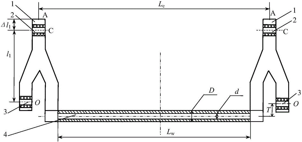
[0050] Example 1: The structure of an externally offset non-coaxial cab stabilizer bar system is symmetrical, as shown in figure 2 As shown, it includes: swing arm 1, suspension rubber bushing 2, torsion rubber bushing 3, torsion tube 4; wherein, the torsion tube 4 is not coaxial with the torsion rubber bushing 3, and the external offset of the torsion tube 4 is T =30mm; the distance L between the left and right swing arms 1 c =1550mm, that is, the suspension distance of the stabilizer bar; the distance between the suspension rubber bushing 2 and the torsion rubber bushing 3, that is, the length of the swing arm l 1 =380mm; the distance from the installation position C of the swing arm suspension to the outermost end A Δl 1 =47.5mm; the length L of the twisted tube 4 w =1500mm, inner diameter d=35mm, outer diameter D=50mm, elastic modulus E=200GPa, Poisson’s ratio μ=0.3; the structure and material properties of the left and right four rubber bushes are exactly the same, as ...

Embodiment 2

[0088] Embodiment 2: The structural form of an externally biased non-coaxial cab stabilizer bar system is the same as that of Embodiment 1, such as figure 2 As shown, where the torsion tube 4 is not coaxial with the torsion rubber bushing 3, the external offset of the torsion tube T=30mm; the distance L between the left and right swing arms 1 c =1400mm, that is, the suspension distance of the stabilizer bar; the distance between the suspension rubber bushing 2 and the torsion rubber bushing 3, that is, the length of the swing arm l 1 =350mm, the distance Δl from the suspension installation position C of the swing arm to the outermost end A 1 =52.5mm; the length L of the torsion tube 4 w =1000mm, inner diameter d=42mm, outer diameter D=50mm; the structures of the left and right four rubber bushes are exactly the same, such as image 3 Shown; Among them, the inner circle diameter d of the inner circle sleeve 5 x =35mm, wall thickness δ=5mm; length L of rubber sleeve 6 x =40...


PUM


Abstract

The invention discloses a method for calculating the deformation of an external bias non-coaxial cab stabilizer bar system and belongs to the technical field of vehicle cab suspension. The deformation of the external bias non-coaxial cab stabilizer bar system can be analyzed and calculated based on the structural parameters, material property parameters and borne loads of an external bias non-coaxial cab stabilizer bar and a rubber bushing according to the equivalent line rigidity of a torsion tube, the load parameters of a torsion rubber bushing, and the radial rigidity and combined equivalent line rigidity of the rubber bushing. Through practical calculation and ANSYS simulation verification, an accurate and reliable calculation value of the external bias non-coaxial cab stabilizer bar system can be obtained with the method, a reliable technical foundation is laid for analytical design of the external bias non-coaxial cab stabilizer bar system and development of CAD design software, and then the design level and product performance of the stabilizer bar and vehicle traveling smoothness are improved, design and test expenses are reduced, and product development speed is increased.

Description

technical field [0001] The invention relates to a vehicle cab suspension, in particular to a calculation method for deformation of an externally biased non-coaxial cab stabilizer bar system. Background technique [0002] In the actual design of the cab suspension and stabilizer bar system, in order to reduce the pitching motion of the cab, a torsion tube externally offset non-coaxial cab stabilizer bar is usually used, that is, the center of the torsion tube and the cab stabilizer bar swing arm The center of torsion of the wheel is not coaxial, which not only provides roll stiffness for the cab and reduces the roll motion of the cab, but also provides a certain pitch stiffness to reduce the pitch motion of the cab. However, due to the constraints of the analytical calculation of the deformation of the rubber bushing, the bending and torsion of the stabilizer bar, and the mutual coupling of loads, it has not been possible to give a reliable calculation of the deformation of t...

Claims


Application Information

Patent Timeline
Patent Type & Authority Applications(China)
IPC IPC(8): G06F17/50
CPCG06F30/15G06F30/23G06F30/367
Inventor 周长城赵雷雷赵光福于曰伟初振美袁光明汪晓王凤娟
Owner SHANDONG UNIV OF TECH
Learn More