Continuous ramming type seismic source device

A technology of ramming source and shaft connection, which is applied in the direction of measuring devices, seismology, instruments, etc., can solve the problems of delay in signal excitation and output, poor quality of reflected signals, and insufficient exploration depth, etc., so as to prolong the use time of equipment , increase reliability, and solve the effect of low excitation energy

Active Publication Date: 2016-11-09
SOUTHWEST PETROLEUM UNIV
View PDF8 Cites 2 Cited by
  • Summary
  • Abstract
  • Description
  • Claims
  • Application Information

AI Technical Summary

Problems solved by technology

However, the traditional hammer-type vibrator can only hit the ground with a single excitation. In this way, the excitation energy of the source equipment is proportional to the mass of the hammer. However, the current small-scale mechanical vibrator is often limited by the mass so that the excitation energy Insufficient, resulting in insufficient exploration depth
In addition, the heavy hammer source also has shortcomings such as low excitation efficiency and delay in signal excitation and output, resulting in poor quality of reflected signals collected by the geophone
The ramming source is a new type of source equipment with the characteristics of simple structure and low signal-to-noise ratio. It decodes continuous small-energy pulse signals to simulate larger-energy pulse signals through frequency-sweeping shock technology to achieve increased The purpose of exploring the depth, while domestic research in this field is still in its infancy

Method used


Image

  • Continuous ramming type seismic source device
  • Continuous ramming type seismic source device
  • Continuous ramming type seismic source device

Examples


Embodiment Construction

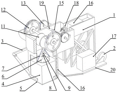
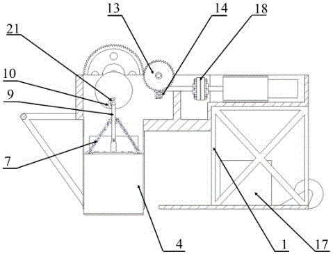
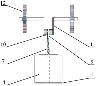
[0017] The present invention will be further described below in conjunction with the accompanying drawings and embodiments.

[0018] like figure 1 , figure 2 , image 3 , Figure 4 , Figure 5 As shown, a continuous tamping type seismic source device of the present invention is mainly composed of a frame 1, wheels 2, handrails 3, a weight 4, a shaft-connected bottom plate 5, a baffle plate 6, a return spring 7, a pin shaft 8, and a T-shaped Rod 9, semicircle arc draw-in groove 10, crankshaft 11, bull gear 12, pinion 13, worm gear 14, worm screw 15, three-phase asynchronous motor 16, counterweight 17 form. There is a central hole in the middle of the weight 4, which is fixed on the shaft-connected bottom plate 5 through the baffle plate 6; the shaft-connected bottom plate 5 is connected with the T-shaped bar 9 through the pin shaft 8; the T-shaped bar 9 is fixed on the crankshaft 11 The semi-arc draw-in groove 10 forms intermittent motion mechanism; The whole device is fi...


PUM


Abstract

The invention relates to a continuous ramming type seismic source device, which is mainly composed of a rack, wheels, a handrail, a heavy hammer, a connecting shaft type bottom plate, a baffle plate, a reset spring, a hinge pin, a T-shaped rod, a semicircular arc clamping groove, crank shafts, a big gear, a small gear, a worm wheel, a worm, a three-phase asynchronous motor and a counter weight, and is characterized in that the middle part of the heavy hammer is provided with a center hole, and the heavy hammer is fixed on the connecting shaft type bottom plate through the baffle plate; the connecting shaft bottom plate is connected with the T-shaped rod through the hinge pin; the T-shaped rod and the semicircular arc clamping groove fixed on the crank shafts form an intermittent motion mechanism; the whole device is fixed on the rack equipped with the handrail and the wheels; and the three-phase asynchronous motor drives the two crank shafts, which are arranged in a left-right symmetric manner and are fixedly connected to the semicircular arc clamping groove, to rotate. The continuous ramming type seismic source device enables the heavy hammer to ram the ground continuously so as to generate continuous controllable pulse signals, and has the advantages of high impact efficiency, adjustable interval, accurate impact force and time-delay-free output signal; and the continuous ramming type seismic source device is small in size, simple in structure, convenient to transport and transfer, and applicable to a complex terrain where field large-scale seismic source equipment cannot operate.

Description

technical field [0001] The invention relates to a continuous ramming seismic source device, which is mainly used for geological investigation, coal seam exploration and shallow layer exploration, and belongs to the technical field of seismic exploration equipment. Background technique [0002] With the increasing awareness of environmental protection at home and abroad, traditional explosive sources have been gradually replaced by non-explosive sources that have less impact on the environment due to their environmental damage and potential safety hazards. In areas with open and flat terrain far away from cities, large-scale vibration excitation equipment represented by hydraulic vibrators has achieved good field application results, but this equipment itself also has disadvantages such as high cost, high energy consumption, and high emissions. . For some areas with complex terrain and relatively dense population, the equipment is often required to have the characteristics o...

Claims


Application Information

Patent Timeline
Patent Type & Authority Applications(China)
IPC IPC(8): G01V1/147
CPCG01V1/147
Inventor 李琴张凯黄志强李刚
Owner SOUTHWEST PETROLEUM UNIV
Why Eureka
Try Eureka