Liquid level detection method and liquid level sensor
A liquid level sensor and liquid level detection technology, which is used in buoy liquid level indicators, liquid/fluid solid measurement, instruments, etc. The measurement method is concise, the effect of solving the stuck float, and the measurement accuracy is high
- Summary
- Abstract
- Description
- Claims
- Application Information
AI Technical Summary
Problems solved by technology
Method used
Image

Examples
Embodiment 1
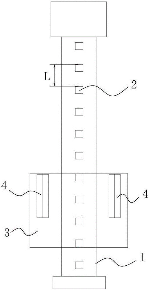
[0039] The preferred embodiment discloses a liquid level detection method and a liquid level sensor for realizing the liquid level detection method. Such as figure 1 As shown, the liquid level sensor includes an electronic tube 1, in which a plurality of magnetoresistive elements 2 are sequentially arranged in the longitudinal direction, and a buoy 3 is rotatably sleeved on the outside of the electronic tube 1, and two magnets 4 are arranged on the buoy 3. The N poles of each magnet 4 are all facing the magnetoresistive element 2 or the S poles are all facing the magnetoresistive element 2; the distance between two adjacent magnetoresistive elements 2 is L, and the length of each magnet 4 is equal to 2L. Multiple magnetoresistive elements 2 are arranged at equal intervals to reduce the difficulty of measurement and calculation.
[0040] In this liquid level detection method, two magnets 4 are oppositely arranged with the same pole to form a magnetic field. When the position o...
Embodiment 2
[0075] This preferred embodiment discloses a liquid level detection method, the principle of which is basically the same as that of the preferred embodiment 1, except that only one magnetoresistive element is used for detection. The liquid level detection method comprises the following steps:
[0076] Step T1: When not affected by the magnetic field, record the output voltage value of the first magnetoresistive element 21 as V 1Initial ;
[0077] Step T2: The magnet 4 moves with the buoy 3. When the first magnetoresistive element 21 is located between the two magnets 4, this position is recorded as the current position. At this time, the output voltage value of the first magnetoresistive element 21 is recorded as V 1Current ;
[0078] Step T3: Using the output voltage value V 1Current and V 1Initial The distance H between the first reluctance element 21 and the plane where the specified position on the magnet 4 is calculated along the moving direction of the buoy 3; the sp...
Embodiment 3
[0081] This preferred embodiment discloses a liquid level sensor whose structure is basically the same as that of the liquid level sensor in the preferred embodiment 1, except that the distance between two adjacent magnetoresistive elements 2 is L, and the length of the magnet 4 is 2L, but the distance between the two magnets 4 is not 2L. The liquid level detection method corresponding to the liquid level sensor of this structure is still that two magnets 4 arranged oppositely form a magnetic field, and when the position of the buoy 3 changes, the magnetic field also changes position accordingly, and the magnetoresistive elements 2 at different positions detect the magnetic field strength Change and output a linear detection result, and calculate the liquid level height value according to the detection result, but the formula used in the detection method needs to be corrected and changed on the basis of formula 1 to formula 5.
PUM
 Abstract
Description
Claims
Application Information
 - R&D
- Intellectual Property
- Life Sciences
- Materials
- Tech Scout
- Unparalleled Data Quality
- Higher Quality Content
- 60% Fewer Hallucinations
Browse by: Latest US Patents, China's latest patents, Technical Efficacy Thesaurus, Application Domain, Technology Topic, Popular Technical Reports.
© 2025 PatSnap. All rights reserved.Legal|Privacy policy|Modern Slavery Act Transparency Statement|Sitemap|About US| Contact US: help@patsnap.com