
Interference fringe image splicing method of inclined entering type laser interferometry measurement

A technology of interference fringes and laser interference, which is applied in the field of image processing, can solve the problems of affecting measurement accuracy and low processing accuracy in fringe-dense areas

Active Publication Date: 2016-11-09
XI'AN POLYTECHNIC UNIVERSITY
View PDF4 Cites 8 Cited by
  • Summary
  • Abstract
  • Description
  • Claims
  • Application Information

AI Technical Summary

Problems solved by technology

[0008] The purpose of the present invention is to provide a splicing method of interference fringe images in oblique laser interferometry measurement, which can realize the splicing and reconstruction of shape error information in multiple interference fringe images with different main optical axis positions, and solve the problems of the prior art. Low processing accuracy in the fringe dense area of ​​the medium interference fringe image and the problem that affects the final measurement accuracy

Method used


Image

  • Interference fringe image splicing method of inclined entering type laser interferometry measurement
  • Interference fringe image splicing method of inclined entering type laser interferometry measurement
  • Interference fringe image splicing method of inclined entering type laser interferometry measurement

Examples


Embodiment Construction

[0070] The present invention will be described in detail below in conjunction with the accompanying drawings and specific embodiments.

[0071] The splicing method of the interference fringe image in the oblique laser interferometry measurement of the present invention is specifically implemented according to the following steps:

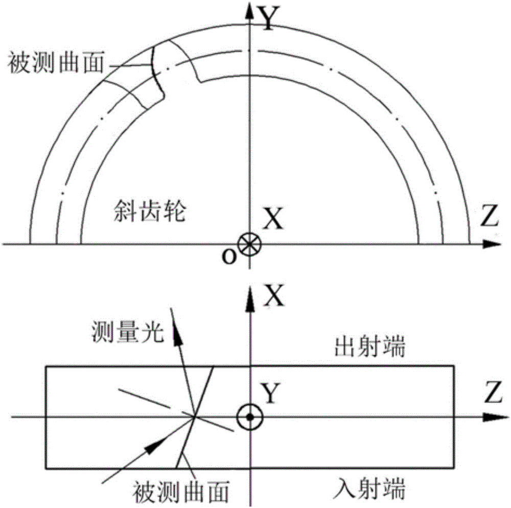
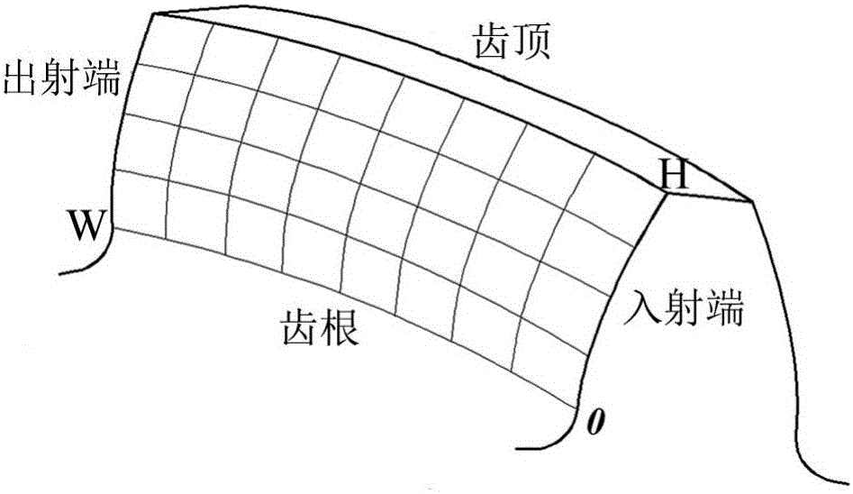
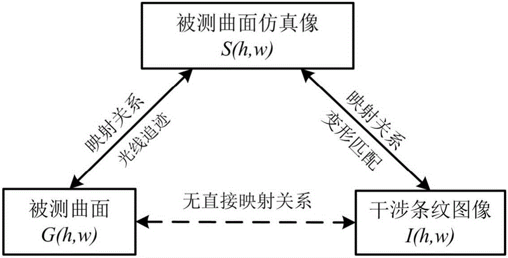
[0072] First of all, taking the helical gear tooth surface as the measurement object, the coordinate system of the measurement system can be as follows figure 1 As shown, the measured surface is divided into W parts in the X-axis direction and H parts in the Y-axis direction, that is to say, the measured surface is divided into (W+1)×(H+1) parts grid points, such as figure 2 As shown; any grid point is marked as G(h,w), h=0,1,...,H, w=0,1,...,W, and its space coordinate is marked as D (h,w) ; The normal direction of any grid point G(h,w) is denoted as n (h,w) , all algebraic symbols used are summarized in Table 1, as shown in Table 1.

[0073] ...


PUM


Abstract

The invention discloses an interference fringe image splicing method of inclined entering type laser interferometry measurement. The interference fringe image splicing method is characterized in that a helical gear tooth flank is used as a measurement object, and a measured surface is equally divided into W parts in an X axis direction, and is equally divided into H parts in a Y axis direction, and therefore the measured surface is divided into (W+1)*(H+1) grid points; any one grid point is marked to be G (h,w), h=0,1,..,H, w=0,1,..,W, and the space coordinate is marked as D (h,w); the normal direction of any one grid point G (h,w) is marked as n (h,w), and space positions of measured curve surfaces are used as splicing references, and registration between various interference fringe images and the measured curve surfaces is carried out; determining is carried out based on the processing reliability of the widths of the fringes; a changing coordinate system model is established; the resampling of the shape errors of the measured curve surfaces is carried out to complete the splicing of the interference fringe images. The splicing method provided by the invention is capable of realizing the splicing and the reconstructing of the shape error information of the various interference fringe images having main optical axes on different positions.

Description

technical field [0001] The invention belongs to the technical field of image processing methods, and in particular relates to a splicing method of interference fringe images in oblique-entry laser interferometry measurement. Background technique [0002] Laser interferometry has the advantages of fast, non-contact and high precision. It is an effective method to measure the shape error of complex curved surfaces (such as: gear tooth surface, inner surface of dynamic and static pressure bearings, etc.). [0003] In the existing technology, based on the improved Mach-Zehnder laser interferometer, the measurement optical path can be built and the interference fringe pattern of the measured surface can be taken; when the measured surface is too wide or the height difference is large, the measurement system The optical path difference between the object optical path and the reference optical path varies greatly in the entire area of ​​the measured surface. At the center of the op...

Claims


Application Information

Patent Timeline
IPC IPC(8): G01B11/24G06T3/40
CPCG06T3/4038G01B11/2416G01B11/2441
Inventor 杨鹏程刘洋方素平胥光申肖渊朱新栋
Owner XI'AN POLYTECHNIC UNIVERSITY
Learn More