
Device for realizing injection control policy of oil injector

A control strategy, fuel injector technology, applied in the direction of fuel injection control, fuel injection device, electrical control, etc., can solve the problems of combustion phase fluctuation, poor atomization of fuel injection, emission of particulates, etc.

Active Publication Date: 2016-11-09
HUNAN UNIV
View PDF5 Cites 1 Cited by
  • Summary
  • Abstract
  • Description
  • Claims
  • Application Information

AI Technical Summary

Problems solved by technology

[0004] In order to overcome the technical problems existing in the prior art, such as poor atomization of direct injection in cylinders, particles emitted by direct injection in cylinders, and fluctuations in combustion phases, the present invention provides a device for realizing the injection control strategy of the fuel injector

Method used


Image

  • Device for realizing injection control policy of oil injector
  • Device for realizing injection control policy of oil injector
  • Device for realizing injection control policy of oil injector

Examples


Embodiment Construction

[0028] The technical solutions of the present invention will be described in detail below in conjunction with the accompanying drawings and embodiments.

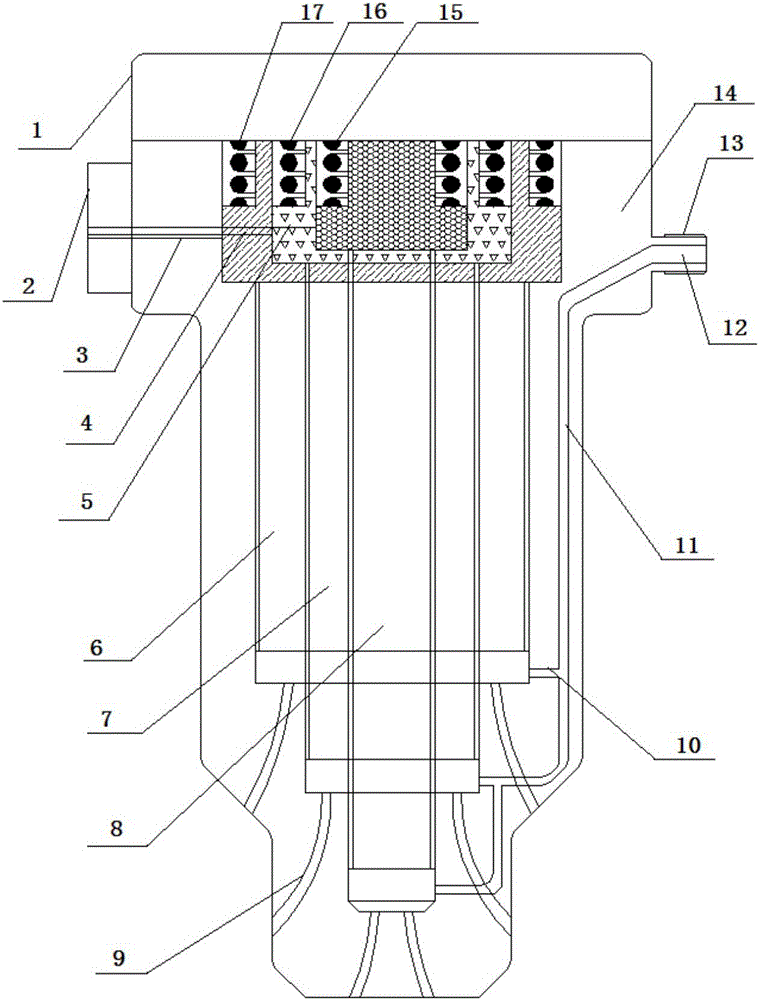
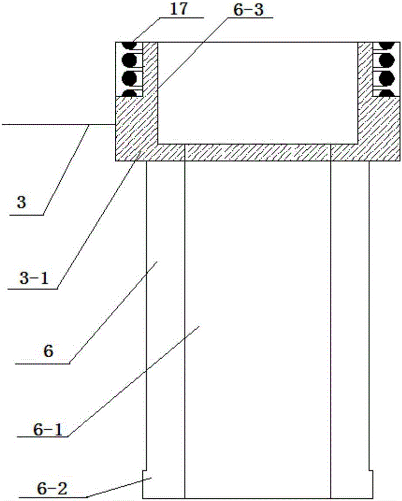
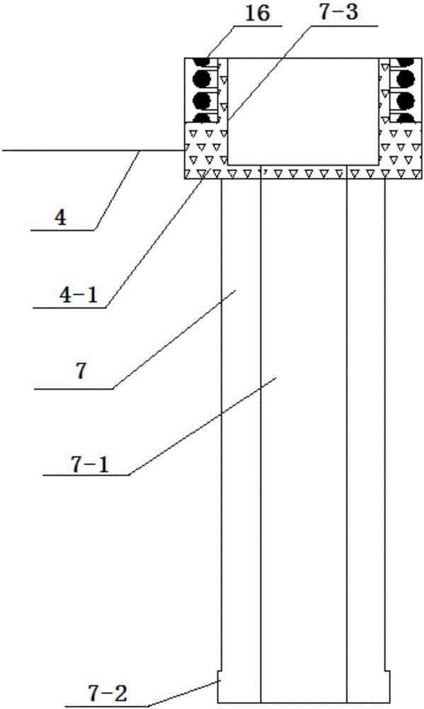
[0029] Such as figure 1 As shown, a device for realizing the injection control strategy of the fuel injector in this embodiment includes: the fuel injector end cover 1, the fuel injector electromagnetic control interface 2, the fuel injector pre-injection electromagnetic switch 3, the fuel injector rear Injection electromagnetic switch 4, injector main injection electromagnetic switch 5, injector pre-injection lever 6, injector rear injection lever 7, injector main injection lever 8, high-pressure oil injection hole 9, Fuel injection oil channel branch 10, fuel injector main fuel oil channel 11, injector main fuel oil channel inlet 12, injector interface thread 13, injector main body 14, injector main fuel injection rod spring 15, Injector rear fuel injection rod spring 16, fuel injector pre-injection rod spring 17.

[003...


PUM


Abstract

The invention relates to a device for realizing an injection control policy of an oil injector. The device comprises an oil injector end cover, an oil injector electromagnetic control device, an oil injector oil preinjecting rod, an oil injector back oil injecting rod, an oil injector main oil injecting rod, a high-pressure oil injecting hole, an oil injecting way branch, an oil injector main oil way, an oil injector main oil way inlet, an oil injector body and an oil injector injecting rod spring; the magnetism of the oil injector electromagnetic control device is changed through controlling connection and disconnection of the oil injector electromagnetic control device; and under the effect of electromagnetic force, the oil injector oil preinjecting rod, the oil injector back oil injecting rod and the oil injector main oil injecting rod upwards move to realize preinjection, back injection and main injection. The device realizes multiple times of precise injection of the oil injector, can control the combustion phase and the combustion temperature, realizes sufficient oil combustion, improves the in-cylinder thermotechnical conversion efficiency, improves the oil energy utilization rate, realizes the in-cylinder clean combustion, reduces generation of pollutants, and realizes energy conservation and emission reduction.

Description

technical field [0001] The invention relates to a device for the fuel injection control strategy of an in-cylinder direct-injection gasoline engine fuel injector, in particular to a device for realizing the fuel injector injection control strategy. Background technique [0002] The State Council issued the "Plan", which clarified the overall goal of China's automobile energy-saving standards, requiring the average fuel consumption of new passenger cars to reach 5.0L / 100km in 2020; The energy saving and emission reduction of the internal combustion engine should be controlled from the source, that is, the combustion control at the core of the engine to achieve clean combustion and low emission; For the control strategy of the injector, the injection method has stricter requirements. Multiple injections, namely pre-injection, main injection, post-injection and other control methods, are used to achieve multiple precise injections and precise control of the injector; increase t...

Claims


Application Information

Patent Timeline
Patent Type & Authority Applications(China)
IPC IPC(8): F02D41/38F02M61/16F02M51/06
CPCF02D41/38F02M51/0617F02M61/16
Inventor 付建勤段雄波刘敬平周峰舒俊王书千
Owner HUNAN UNIV
Learn More