magnetic moxibustion needle
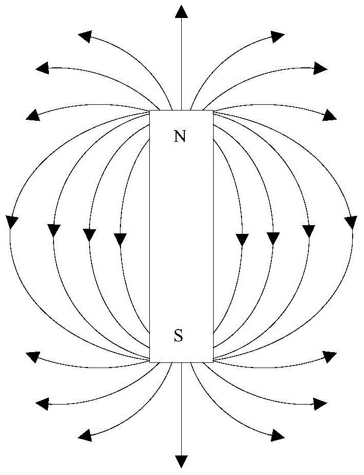
A magnetic moxibustion and magnetic sleeve technology, applied in the field of magnetic moxibustion needles, can solve the problems of poor magnetic moxibustion treatment effect, weak magnetic induction intensity, and dispersion of magnetic force lines of magnetic moxibustion needles, and achieve better therapeutic effect, enhanced magnetic induction intensity, and increased penetration effect of distance
- Summary
- Abstract
- Description
- Claims
- Application Information
AI Technical Summary
Problems solved by technology
Method used
Image
Examples
Embodiment 1
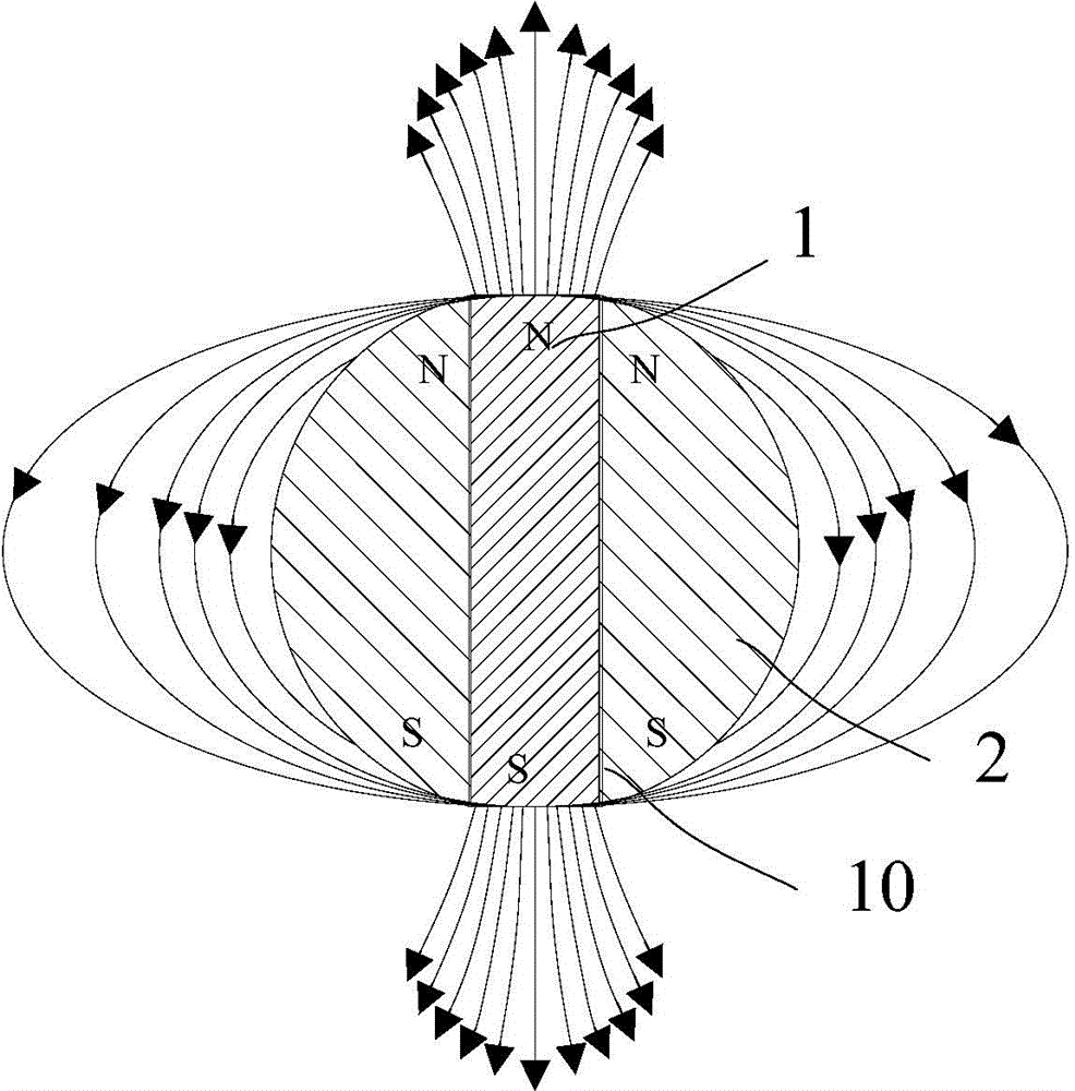
[0024] Such as figure 2 As shown, the present invention provides a magnetic moxibustion needle, comprising a magnetic core 1 and a magnetic sleeve 2 sleeved on the magnetic core 1; the magnetic induction of the magnetic core 1 is greater than the magnetic induction of the magnetic sleeve 2; the magnetic core 1 It is fixedly connected with the magnetic sleeve 2; the magnetic core 1 is rod-shaped, the N pole and the S pole of the magnetic core 1 are arranged along the axial direction of the magnetic core, and the N pole and the S pole of the magnetic sleeve 2 are in the inner hole of the magnetic sleeve Axially arranged; the N pole of the magnetic core 1 is close to the N pole of the magnetic sleeve 2, and the S pole of the magnetic core 1 is close to the S pole of the magnetic sleeve 2.
[0025] The magnetic moxibustion needle provided by the present invention, through the magnetic sheath 2 set on the magnetic core 1, since the magnetic core 1 and the magnetic sheath 2 are arr...
Embodiment 2 Embodiment 3
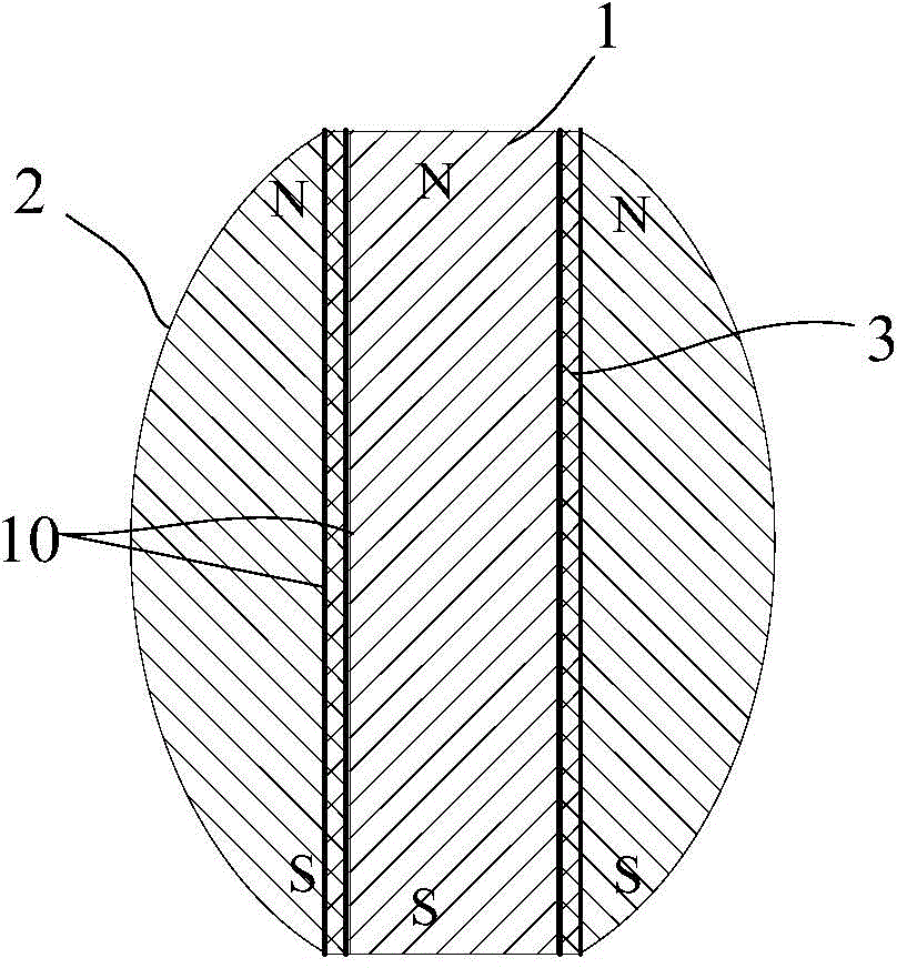
[0030] As another specific implementation manner of the above-mentioned embodiment, such as image 3 , Figure 4 As shown, the magnetic sleeve 2 is in the shape of an ellipsoid, and the inner hole of the magnetic sleeve 2 is arranged along the direction of the major semi-axis or the minor semi-axis of the ellipsoid. The inner hole of the magnetic sleeve 2 is used to pass through the magnetic core 1 . The distribution state of the magnetic force lines of the ellipsoidal magnetic sleeve 2 has a greater effect on the magnetic force lines at the two extremes of the magnetic core body 1 , and is more conducive to the aggregation of the magnetic force lines at the two extreme ends of the magnetic core body. image 3 The inner hole of the middle magnetic sleeve 2 is set along the direction of the major semi-axis of the ellipsoid; Figure 4 The inner hole of the middle magnetic sleeve 2 is arranged along the direction of its minor semi-axis; see the second embodiment image 3 , see...
Embodiment 4 6
[0032] As yet another specific implementation manner of the above-mentioned embodiment, such as Figure 5-7 As shown, the magnetic sleeve 2 is cylindrical, and the inner hole of the magnetic sleeve 2 is arranged along the direction of its central axis. The structure is simple and easy to make.
[0033] As a preferred embodiment of the above implementation, the magnetic core 1 and / or the magnetic sleeve 2 are permanent magnets. Compared with using electromagnets, the structure is simpler and the cost is lower.
[0034] As a preferred implementation of the above-mentioned embodiment, such as Figure 3-7 As shown, there is at least one spacer 3 between the magnetic core 1 and the magnetic sleeve 2, and the spacer 3 is made of a non-magnetic material. are fixedly connected.
[0035] image 3 , Figure 5 The middle isolation sleeve 3 completely isolates the magnetic core 1 and the magnetic sleeve 2; Figure 4 , Image 6 The middle spacer 3 partially isolates the magnetic co...
PUM
 Abstract
Description
Claims
Application Information
 - R&D
- Intellectual Property
- Life Sciences
- Materials
- Tech Scout
- Unparalleled Data Quality
- Higher Quality Content
- 60% Fewer Hallucinations
Browse by: Latest US Patents, China's latest patents, Technical Efficacy Thesaurus, Application Domain, Technology Topic, Popular Technical Reports.
© 2025 PatSnap. All rights reserved.Legal|Privacy policy|Modern Slavery Act Transparency Statement|Sitemap|About US| Contact US: help@patsnap.com


