Energy-saving counter-weight-adjustable elevator

An elevator and counterweight technology, applied in the field of elevators, can solve problems such as endangering passenger safety, power consumption, and weight changes of steel wire ropes, and achieve the effects of increasing safety and comfort, reducing energy consumption, and running smoothly up and down

Inactive Publication Date: 2016-11-09
新疆天山电梯制造有限公司
View PDF8 Cites 1 Cited by
  • Summary
  • Abstract
  • Description
  • Claims
  • Application Information

AI Technical Summary

Problems solved by technology

At present, elevators have been more and more commonly used in high-rise buildings, providing convenience for people to go up and down the stairs. However, the current elevators need to consume electric energy no matter whether they are going up or down. There is no energy recovery device, and the elevator is running During the process, the length of the wire rope on the car side and the counterweight side is constantly changing, which causes the weight of the wire rope on both sides of the traction sheave to change
This change has little effect on the operating performance of the elevator when the lifting height of the elevator is not large, but when the lifting height exceeds a certain height, it will seriously affect the stability of the elevator operation and endanger the safety of passengers. In the case of , the traction machine will be in a heavy load working state, which will cause energy loss

Method used


Image

  • Energy-saving counter-weight-adjustable elevator
  • Energy-saving counter-weight-adjustable elevator

Examples


Embodiment Construction

[0015] The following will clearly and completely describe the technical solutions in the embodiments of the present invention with reference to the accompanying drawings in the embodiments of the present invention. Obviously, the described embodiments are only some, not all, embodiments of the present invention. Based on the embodiments of the present invention, all other embodiments obtained by persons of ordinary skill in the art without making creative efforts belong to the protection scope of the present invention.

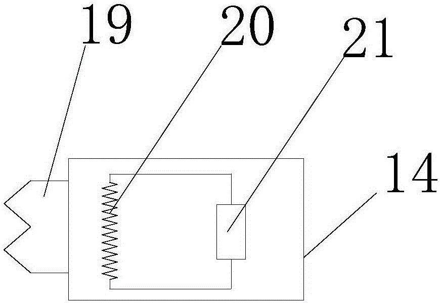
[0016] see Figure 1~2 , in an embodiment of the present invention, an energy-saving elevator with adjustable counterweight includes a box body 2, a counterweight system, a steel wire rope 7, a power generation system, and a traction machine 22. A pressure sensor 1 is provided at the bottom of the box body 2, and the The left and right sides of the top of the box body 2 are respectively provided with a micro motor 3, the output shaft of the micro motor 3 is fi...


PUM


Abstract

The invention discloses an energy-saving counter-weight-adjustable elevator. The elevator comprises a box body, power generation systems and a traction machine, wherein a steel wire rope is arranged at the top end of the box body, one end of the steel wire rope is fixedly connected with the box body, and the other end of the steel wire rope sequentially winds around the traction machine and a transmission wheel to be fixedly connected with a counter-weight system and a main counter-weight; the counter-weight system comprises multiple counter-weights and a counter-weight channel, and each counter-weight comprises an iron core and an electromagnet; the multiple power generation systems are arranged on the outer side of the main counter-weight; and each power generation system comprises a transmission belt, a connecting gear block, a rack, rollers and a power generator, the main counter-weight is fixedly connected with the rack, the rollers are arranged inside the upper end and the lower end of the transmission belt, the power generator is fixedly connected with the roller on the lower side of the transmission belt, and the connecting gear block is arranged on the transmission belt. According to the elevator, centroid adjustment of the box body is realized, the safety and the comfort degree of the elevator are improved, counter-weight adjustment is realized according to the actual load of the elevator, the energy consumption of the elevator is reduced, and energy is saved by the aid of the power generation systems.

Description

technical field [0001] The invention relates to an elevator, in particular to an energy-saving elevator with adjustable counterweight. Background technique [0002] Elevator is a kind of vertical elevator powered by electric motor, equipped with box-shaped gondola, used for multi-storey buildings to take advantage of people or carry goods. A vertical elevator has a car running between at least two vertical or inclination angles of less than 15° rigid guide rails. The size and structure of the car are convenient for passengers to enter and exit or to load and unload goods. It is customary to use elevator as a general term for vertical transportation in buildings regardless of its driving mode. According to the speed, it can be divided into low-speed elevators, fast elevators and high-speed elevators. Hydraulic elevators began to appear in the mid-19th century and are still used in low-rise buildings today. In 1852, E.G. Otis of the United States developed a safety elevato...

Claims


Application Information

Patent Timeline
Patent Type & Authority Applications(China)
IPC IPC(8): B66B11/04B66B7/00
CPCB66B11/04B66B7/00
Inventor 蒯乃鹏沈晓龙阿迪力
Owner 新疆天山电梯制造有限公司
Why Eureka
Try Eureka