
A pop-up slider mechanism for an injection mold

An injection mold, pop-up technology, applied in the field of injection mold structure, can solve the problems of increasing the mold size, failure of fixed mold core-pulling slider, large volume of oil cylinder core-pulling mechanism, etc., to meet the requirements of appearance and movement process smooth effect

Active Publication Date: 2018-04-17
江苏文光模具技术有限公司
View PDF7 Cites 0 Cited by
  • Summary
  • Abstract
  • Description
  • Claims
  • Application Information

AI Technical Summary

Problems solved by technology

[0003] The original core-pulling structure of the fixed mold of the mold uses an oil cylinder to drive the movement of the core-pulling slider to complete the core-pulling and reset actions of the fixed-mould slider. Injection molding can only be produced on the top, and the core-pulling and reset process is unstable, and the fixed-mold core-pulling slider has a potential risk of failure

Method used


Image

  • A pop-up slider mechanism for an injection mold
  • A pop-up slider mechanism for an injection mold

Examples


Embodiment Construction

[0011] The present invention will be described in further detail below in conjunction with the accompanying drawings.

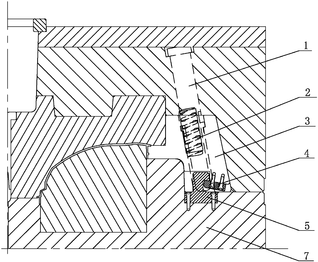
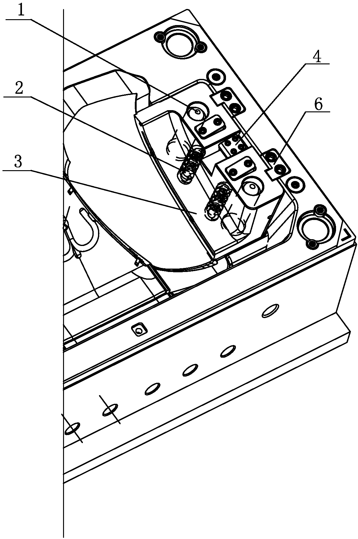
[0012] see figure 1 , 2 , a pop-up slider mechanism for an injection mold, comprising a fixed mold slider 3, an oblique guide post 1 is arranged on the fixed mold slider 3, a spring hole is provided on the fixed mold slider 3, the axis of the spring hole is aligned with the oblique The axes of the guide post 1 are parallel, and the spring hole is provided with a compression spring 2, the compression spring 2 is against the fixed mold slider 3, the upper end of the fixed mold slider 3 is provided with a limit block 6, and the limit block 6 is fixed on the mold frame. Die slide block 3 bottoms are provided with drag hook 5, and drag hook 5 one ends hook drag hook block 4, and drag hook 5 other ends are fixed on the moving mold, and drag hook block 4 is fixed on the fixed mold slide block 3. There are two oblique guide posts 1 and compression springs 2, which ...


PUM


Abstract

The invention discloses a pop-open sliding block mechanism of an injection mold. The pop-open sliding block mechanism comprises a fixed mold sliding block, slider angle pins are arranged on the fixed mold sliding block, spring holes are formed in the fixed mold sliding blocks, and the axes of the spring holes are parallel to those of the slider angle pins. Compression springs are arranged in the spring holes and abut against the fixed mold sliding block, and a limiting block is arranged at the upper end of the fixed mold sliding block and fixed to a mold frame. A pull hook is arranged at the bottom of the fixed mold sliding block. One end of the pull hook hooks a pull hook check block, and the other end of the pull hook is fixed to a moving mold. The pull hook check block is fixed to the fixed mold sliding block. The fixed mold sliding block moves in the axis direction of the slider angle pins under the common action of the pull hook and the springs, the pull hook is separated from the pull hook check block on the fixed mold sliding block, and the fixed mold sliding block only continues to move under the elastic force of the springs till the fixed mold sliding block touches the limiting block; and ribs and clamping pins on the side face of a plastic part are separated out of the fixed mold sliding block, and the core pulling process is completed.

Description

technical field [0001] The invention relates to the injection mold structure of the lampshade of the front headlight of a passenger car, in particular to a core-pulling slider mechanism for fixing the mold of the lampshade. Background technique [0002] Automobile headlights, as functional parts and exterior parts, are increasingly becoming an important part of car styling and overall appearance, so there are higher requirements for the structure and process of plastic parts. The lampshade requires beautiful and novel appearance, smooth surface, transparent and certain strength. The lampshade and the lamp housing are assembled in the form of clips and clips. The state of motion should be stable, reliable and efficient. [0003] The original core-pulling structure of the fixed mold of the mold uses an oil cylinder to drive the movement of the core-pulling slider to complete the core-pulling and reset actions of the fixed-mould slider. Injection molding can only be produced ...

Claims


Application Information

Patent Timeline
Patent Type & Authority Patents(China)
IPC IPC(8): B29C45/33B29C45/40
CPCB29C45/33B29C45/4005
Inventor 邬新桥卢建生薛峰陈栗束伟军戎煜张静蒋桢锋袁建辉
Owner 江苏文光模具技术有限公司
Learn More