Double-horizontal-shaft crossed recurrence continuous vibratory stirring device
A vibrating mixing, twin-shaft technology, applied in cement mixing devices, clay preparation devices, chemical instruments and methods, etc., can solve the problems of delayed working time, unfavorable mixing effect, and difficulty in achieving microscopic uniform mixing of the mixture. Improve stirring quality and stirring efficiency, strengthen circulating flow and diffusion distribution, and promote the effect of circulating cross-propulsion
- Summary
- Abstract
- Description
- Claims
- Application Information
AI Technical Summary
Problems solved by technology
Method used
Image
Examples
Embodiment 1
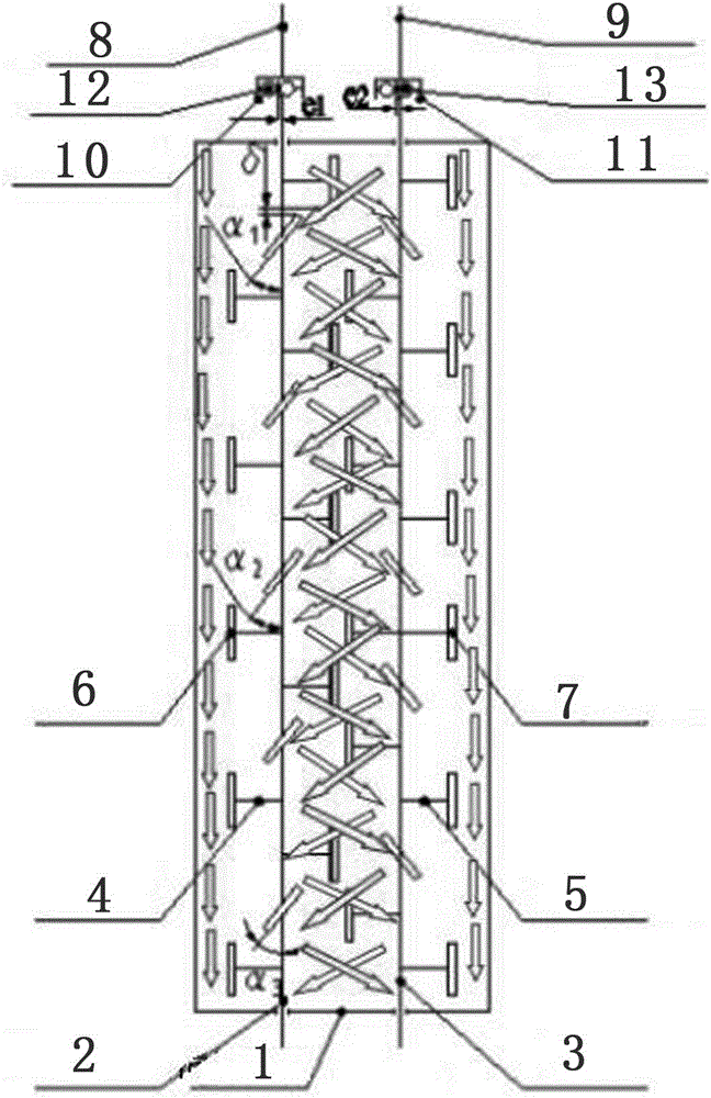
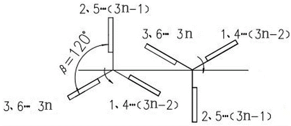
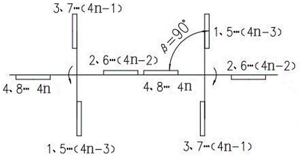
[0032] Such as figure 1 and figure 2 As shown, a double-horizontal shaft cross-recursive continuous vibration stirring device includes a mixing cylinder 1 and a vibration device. The mixing cylinder 1 is provided with a feed end and a discharge end, and the mixing cylinder 1 is equipped with a first A stirring shaft 2 and a second stirring shaft 3, the first stirring shaft 2 and the second stirring shaft 3 have the same structure, both ends of the first stirring shaft 2 and the second stirring shaft 3 are solid structures, the first stirring shaft 2 and the two ends of the second stirring shaft 3 are installed on the feed end and the discharge end respectively, the first stirring arm 4 is installed on the first stirring shaft 2, and the first stirring blade 6 is connected on the first stirring arm 4, The second stirring arm 5 is installed on the second stirring shaft 3, the second stirring arm 5 is connected with the second stirring blade 7, the structure of the first stirring...
Embodiment 2
[0038] The difference between this embodiment and Embodiment 1 is: the installation angle α1 between the first stirring blade section 1 and the axis of the first stirring shaft = 45°, the installation angle between the first stirring blade section 2 and the axis of the first stirring shaft The included angle α2=55°, the installation angle α3=65° between the first stirring blade segment 3 and the axis of the first stirring shaft, the installation angle α′ between the second stirring blade segment 1 and the axis of the second stirring shaft 1=45°, the installation angle α′ between the second stirring blade segment 2 and the axis of the second stirring shaft 2=55°, the installation angle α′ between the second stirring blade segment 3 and the axis of the second stirring shaft 3=65°.
Embodiment 3
[0040] The difference between this embodiment and Embodiment 1 is: the installation angle α1 between the first stirring blade section 1 and the axis of the first stirring shaft = 50°, the installation angle between the first stirring blade section 2 and the axis of the first stirring shaft The included angle α2=60°, the installation angle α3=70° between the first stirring blade segment 3 and the axis of the first stirring shaft, the installation angle α′ between the second stirring blade segment 1 and the axis of the second stirring shaft 1=50°, the installation angle α′ between the second stirring blade segment 2 and the axis of the second stirring shaft 2=60°, the installation angle α′ between the second stirring blade segment 3 and the axis of the second stirring shaft 3=70°.
PUM
 Abstract
Description
Claims
Application Information
 - R&D
- Intellectual Property
- Life Sciences
- Materials
- Tech Scout
- Unparalleled Data Quality
- Higher Quality Content
- 60% Fewer Hallucinations
Browse by: Latest US Patents, China's latest patents, Technical Efficacy Thesaurus, Application Domain, Technology Topic, Popular Technical Reports.
© 2025 PatSnap. All rights reserved.Legal|Privacy policy|Modern Slavery Act Transparency Statement|Sitemap|About US| Contact US: help@patsnap.com


