Clamp for machining side wall of metal pipe

A technology of metal pipes and fixtures, applied in metal processing equipment, metal processing machinery parts, manufacturing tools, etc., can solve the problems of inapplicability, and achieve the effects of automatic adjustment, automatic clamping, and automatic unloading

Active Publication Date: 2016-11-09
东莞福伽轩精密五金模具有限公司
View PDF7 Cites 4 Cited by
  • Summary
  • Abstract
  • Description
  • Claims
  • Application Information

AI Technical Summary

Problems solved by technology

[0004] After the workpiece is uploaded to the fixture by the feeding device, the workpiece is then processed by the processing tool. For the fixture of the workpiece, it is necessary to have a clamping function to automatically unload the workpiece after the processing is completed, which is convenient for the next workpiece. processing, currently there is no fixture applicable to the round tubular workpieces targeted by the present invention

Method used


Image

  • Clamp for machining side wall of metal pipe
  • Clamp for machining side wall of metal pipe
  • Clamp for machining side wall of metal pipe

Examples


Embodiment

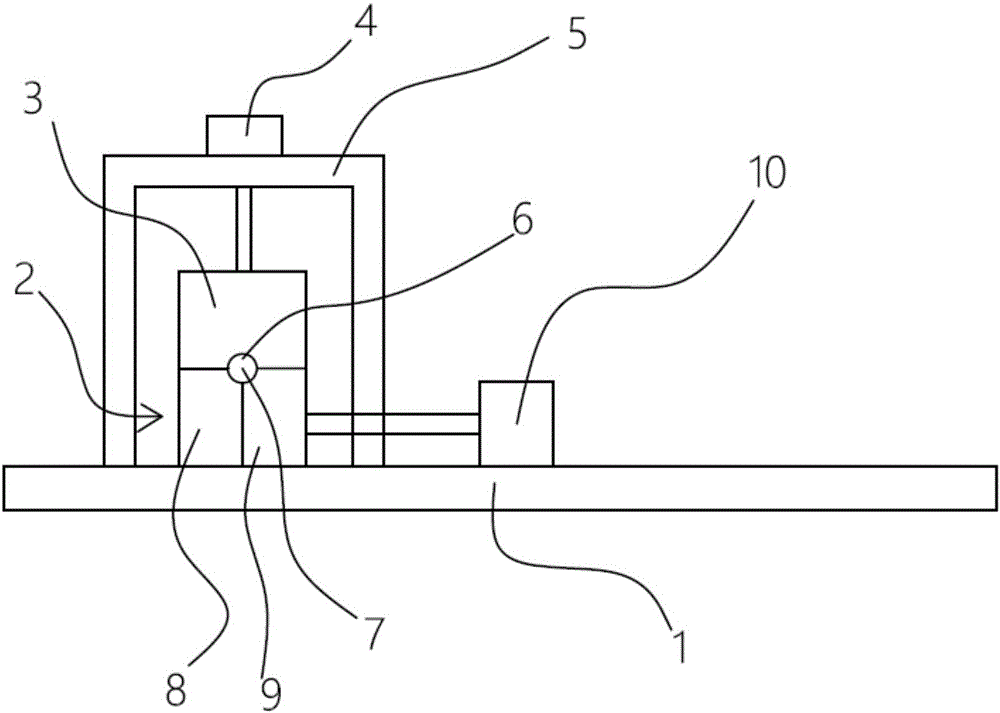
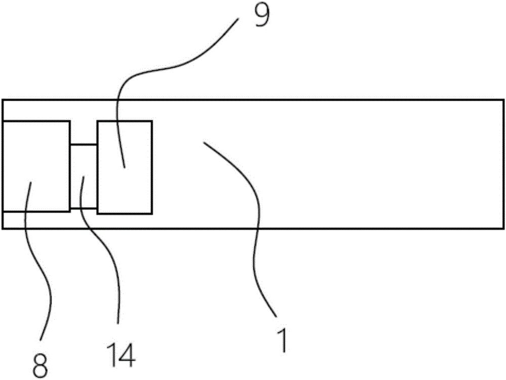
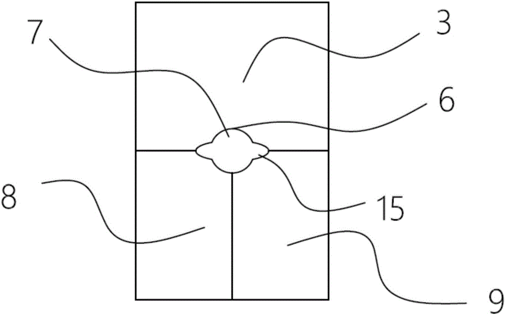
[0027] A fixture for processing the side wall of a metal pipe, such as figure 1 , 2 , 3, 4, and 5, including the base 1, the base 1 is provided with the lower seat 2 of the fixture, and the upper seat 3 of the fixture is located on the lower seat 2 of the fixture and cooperates with the lower seat 2 of the fixture, and the cylinder of the fixture is arranged above the upper seat 3 of the fixture 4. The clamp cylinder 4 is connected through the cylinder frame 5 on the base 1. The clamp cylinder 4 is set downward and its end is connected to the top of the clamp upper seat 3; The fixture half groove 6, the upper and lower fixture half grooves 6 are combined into a fixture groove 7 for clamping the workpiece; the fixture lower seat 2 includes two parts: a fixed part 8 and a moving part 9, the fixed part 8 is fixedly connected with the base 1, and the moving part 9 is slidingly connected with the base 1; the base 1 is also provided with a discharge cylinder 10 on one side of the m...


PUM


Abstract

The invention relates to the technical field of machining, in particular to a clamp for machining the side wall of a metal pipe. The clamp comprises a base, wherein a clamp lower seat and a clamp upper seat which is located on the clamp lower seat and matched with the clamp lower seat are arranged on the base, a clamping cylinder is arranged above the clamp upper seat, the clamping cylinder is connected through a cylinder framework arranged on the base, the clamping cylinder is downwards arranged, and the end part of the clamping cylinder is connected with the top of the clamp upper seat; matched clamp semi-grooves are arranged at the combination parts of the clamp upper seat and the clamp lower seat, and the upper and lower clamp semi-grooves are combined to form a clamp groove used for clamping a workpiece; the clamp lower seat comprises a fixed part and a moving part, the fixed part is fixedly connected with the base, and the moving part is in sliding connection with the base; and the side, located at the moving part, of the base is further provided with an unloading cylinder, the unloading cylinder is horizontally arranged, and the end part of the unloading cylinder is connected with the side surface of the moving part. The clamp realizes automatic workpiece clamping, realizes automatic adjustment on the workpiece and the optimal machining position of machining equipment, and realizes the automatically unloading of the workpiece machined.

Description

technical field [0001] The invention relates to the technical field of mechanical processing, in particular to a clamp for processing the side wall of a metal pipe. Background technique [0002] With the popularization of automation and semi-automation in various industries of the economy, automatic feeding devices have become an indispensable link in the production line. [0003] A kind of workpiece whose raw material is a metal circular tube. After the side of the end is punched, a concave groove is formed on the end. It can be used as a basic hardware for the connection between various cylinders. [0004] After the workpiece is uploaded to the fixture by the feeding device, the workpiece is then processed by the processing tool. For the fixture of the workpiece, it is necessary to have a clamping function to automatically unload the workpiece after the processing is completed, which is convenient for the next workpiece. Processing, currently there is no fixture suitable ...

Claims


Application Information

Patent Timeline
Patent Type & Authority Applications(China)
IPC IPC(8): B23Q3/08
CPCB23Q3/062B23Q3/064B23Q3/08
Inventor 黄春平
Owner 东莞福伽轩精密五金模具有限公司
Why Eureka
Try Eureka