An automatic unloading device

An automatic cutting and barrel technology, applied in metal processing and other directions, can solve the problems of poor transmission guidance of pipe fittings and cylindrical parts, high labor intensity of workers, low work efficiency, etc., and achieves wide application range, compact structure, and reliable cutting. Effect

Active Publication Date: 2018-05-18
东莞市晋诚机械有限公司
View PDF4 Cites 0 Cited by
  • Summary
  • Abstract
  • Description
  • Claims
  • Application Information

AI Technical Summary

Problems solved by technology

[0002] After the chamfering machine tool chamfers the pipe fittings, cylindrical parts and other materials, the traditional method is to manually unload the processed materials. Using manual unloading, the labor intensity of the workers is high, the work efficiency is low, and there are certain safety hazards
[0003] Most of the existing chamfering machines are equipped with automatic loading and unloading devices, which overcome the deficiencies of traditional manual loading and unloading to a certain extent, but generally have large volume, poor flexibility, narrow application range, and the transmission of materials such as pipe fittings and cylindrical parts. Poor performance and other shortcomings, can not meet the needs of production

Method used


Image

  • An automatic unloading device
  • An automatic unloading device
  • An automatic unloading device

Examples


Embodiment Construction

[0019] In order to facilitate the understanding of those skilled in the art, the present invention will be further described below in conjunction with the embodiments and accompanying drawings, and the contents mentioned in the embodiments are not intended to limit the present invention.

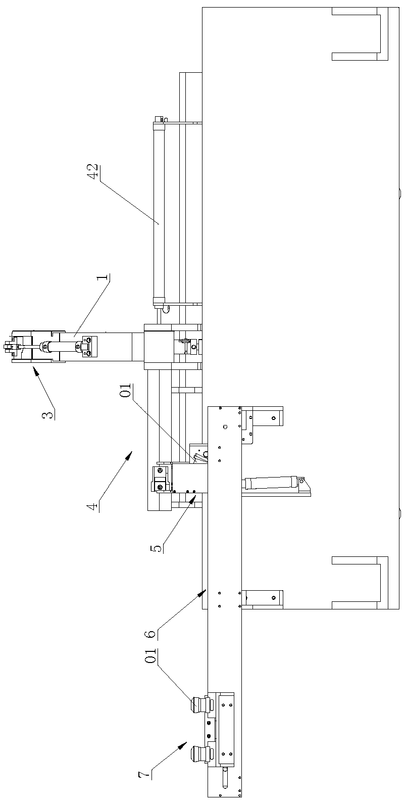
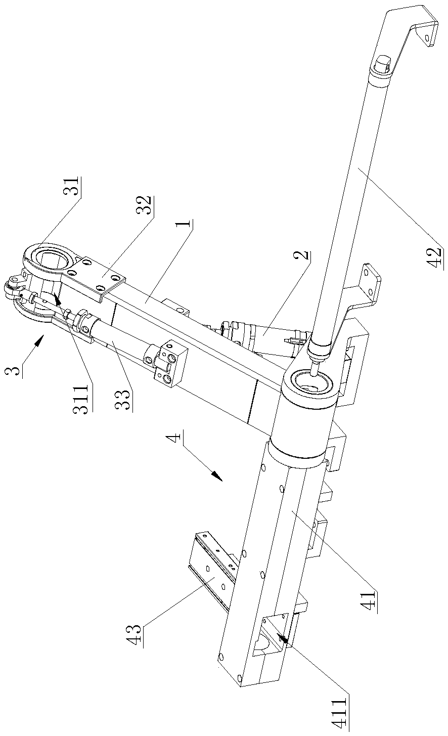
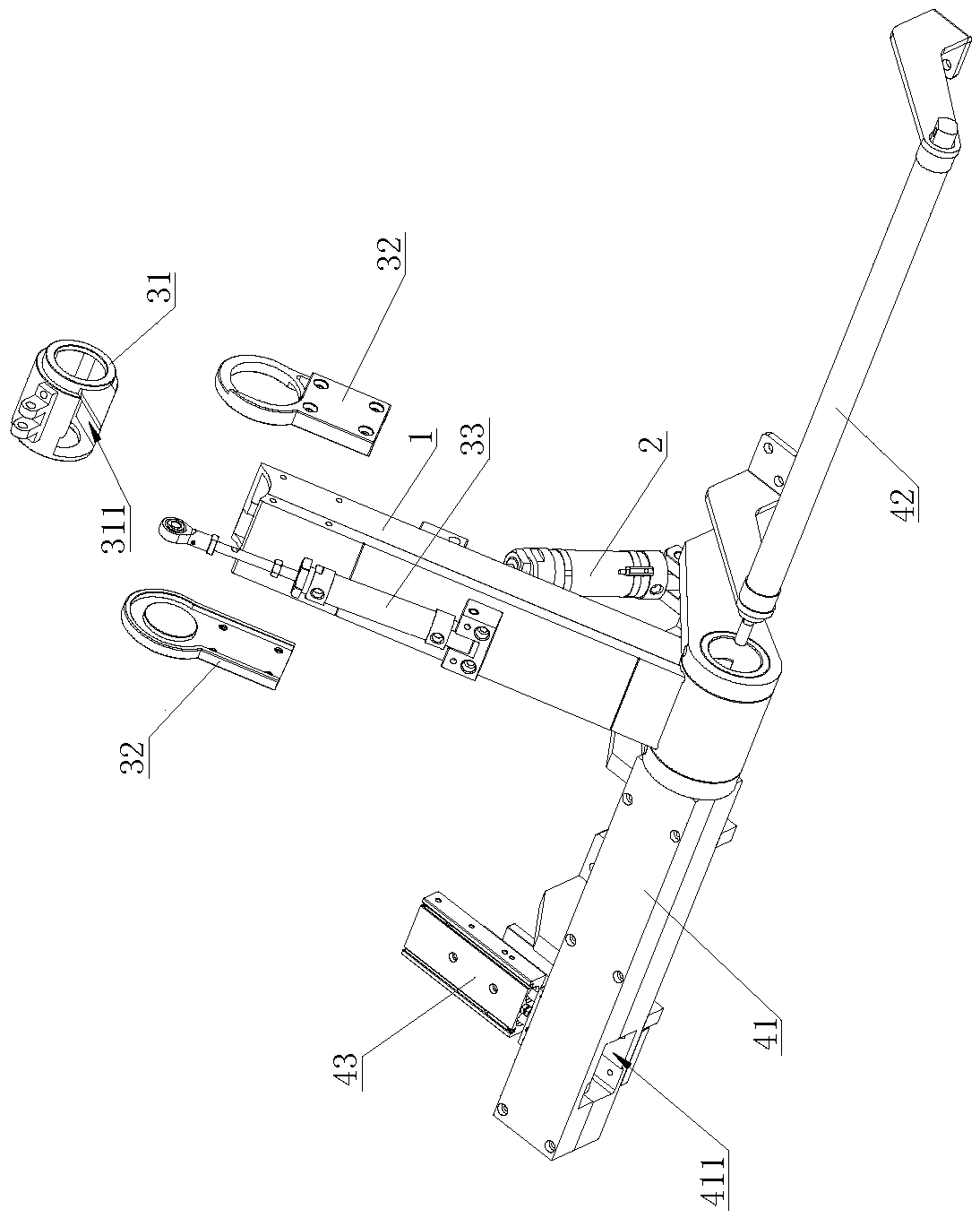
[0020] Such as Figure 1 to Figure 5 As shown, an automatic unloading device includes a lifting barrel 1, a lifting drive mechanism 2 for driving one end of the lifting barrel 1 to lift and receive materials, and a valve mechanism 3 arranged on the lifting barrel 1. The valve mechanism 3 It includes a rotating barrel 31 arranged at the material inlet of the lifting barrel 1, a rotating barrel mounting plate 32 for installing the rotating barrel 31 on the lifting barrel 1, and a valve drive mechanism 33 for driving the rotating barrel 31 to rotate , the rotating barrel 31 is provided with a material outlet 311 . The lifting driving mechanism 2 and the valve driving mechanism 33 can be realiz...


PUM


Abstract

The invention relates to the technical field of discharging equipment, in particular to an automatic discharging device. The automatic discharging device comprises a lifting material cylinder, a lifting driving mechanism used for driving one end of the lifting material cylinder to ascend and descend to collect material, and a valve mechanism arranged on the lifting material cylinder. The valve mechanism comprises a rotating material cylinder arranged at a feeding port of the lifting material cylinder, a rotating material cylinder installation plate used for installing the rotating material cylinder to the lifting material cylinder, and a valve driving mechanism used for driving the rotating material cylinder to rotate. The rotating material cylinder is provided with a material outlet. The automatic discharging device is compact in structure and convenient to install and transport, one end of the lifting material cylinder is adopted to ascend and descend to be aligned with materials, the adjustable range of the device is wide, flexible use can be achieved, and the automatic discharging device can adapt to discharging of more types of machines and is wide in application range. The valve driving mechanism controls the circulation of the materials through rotation of the rotating material cylinder, the materials are controlled and are prevented from rolling at will, and therefore discharging is reliable; and the materials roll in the lifting material cylinder and are blocked and guided through the lifting material cylinder, and therefore the materials are reliably conveyed.

Description

technical field [0001] The invention relates to the technical field of unloading equipment, in particular to an automatic unloading device. Background technique [0002] After the chamfering machine tool chamfers the pipe fittings, cylindrical parts and other materials, the traditional method is to manually unload the processed materials. Using manual unloading, the labor intensity of the workers is high, the work efficiency is low, and there are certain safety hazards. [0003] Most of the existing chamfering machines are equipped with automatic loading and unloading devices, which overcome the deficiencies of traditional manual loading and unloading to a certain extent, but generally have large volume, poor flexibility, narrow application range, and the transmission of materials such as pipe fittings and cylindrical parts. Poor performance and other shortcomings, can not meet the needs of production. Contents of the invention [0004] The technical problem to be solved ...

Claims


Application Information

Patent Timeline
Patent Type & Authority Patents(China)
IPC IPC(8): B23D79/00B23Q7/00
CPCB23D79/00B23Q7/00
Inventor 王南艳谢永福
Owner 东莞市晋诚机械有限公司
Why Eureka
Try Eureka