
Multi-beam combined angle measuring angle and point trajectory fusion method of MIMO radar targets under orthogonal waveforms

A radar target and orthogonal waveform technology, applied in the radar field, can solve the problems of different centralized MIMO radar pulse pressure coefficients, the loss of pulse synthesis in orthogonal waveform receiving and processing, and the difficulty of applying single pulse angle measurement technology, etc., to achieve real-time performance Strong, reduce hardware complexity, ensure the effect of accuracy

Active Publication Date: 2016-11-02
XIDIAN UNIV
View PDF6 Cites 17 Cited by
  • Summary
  • Abstract
  • Description
  • Claims
  • Application Information

AI Technical Summary

Problems solved by technology

[0005] However, due to the different transmit waveforms of the array elements contained in the centralized MIMO radar under the orthogonal waveform, pulse synthesis is required, so that the pulse pressure coefficients of the echoes in each direction of the centralized MIMO radar are different; and in actual processing, due to The target orientation is unknown, so that there is a pulse synthesis loss in the receiving and processing of the orthogonal waveform, which makes it difficult to apply the single-pulse angle measurement technology on the traditional phased array radar
In addition, in the pan-detection processing mode, different beams may receive reflected energy from the same target, especially when the receiving sidelobe is high and the receiving gain fluctuates. Possibility of police increased

Method used


Image

  • Multi-beam combined angle measuring angle and point trajectory fusion method of MIMO radar targets under orthogonal waveforms
  • Multi-beam combined angle measuring angle and point trajectory fusion method of MIMO radar targets under orthogonal waveforms
  • Multi-beam combined angle measuring angle and point trajectory fusion method of MIMO radar targets under orthogonal waveforms

Examples


Embodiment Construction

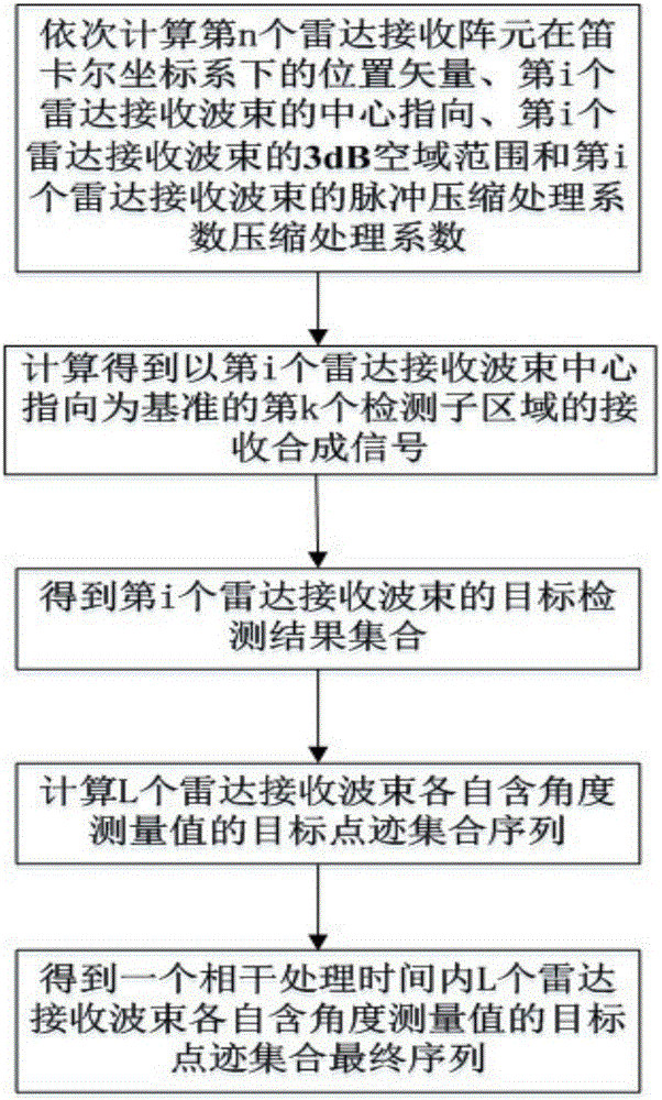
[0033] refer to figure 1 , is a flow chart of the multi-beam joint angle measurement and point-track fusion method of the MIMO radar target under a kind of orthogonal waveform of the present invention; the multi-beam joint target angle measurement and point-track fusion method comprises the following steps:

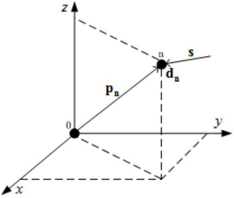
[0034] Step 1. Establish the geometric model of the radar in the Cartesian coordinate system, and respectively determine the number of radar receiving array elements N, the number of radar receiving beams L and the radar power radiation airspace range Ω in the Cartesian coordinate system, and set the nth The transmitted signal of the radar receiving element is denoted as s n , and then sequentially calculate the position vector p of the nth radar receiving element in the Cartesian coordinate system n , the center of the receiving beam of the i-th radar points to θ i , the 3dB airspace range of the i-th radar receiving beam Ω i and the pulse compression processing coeff...


PUM


Abstract

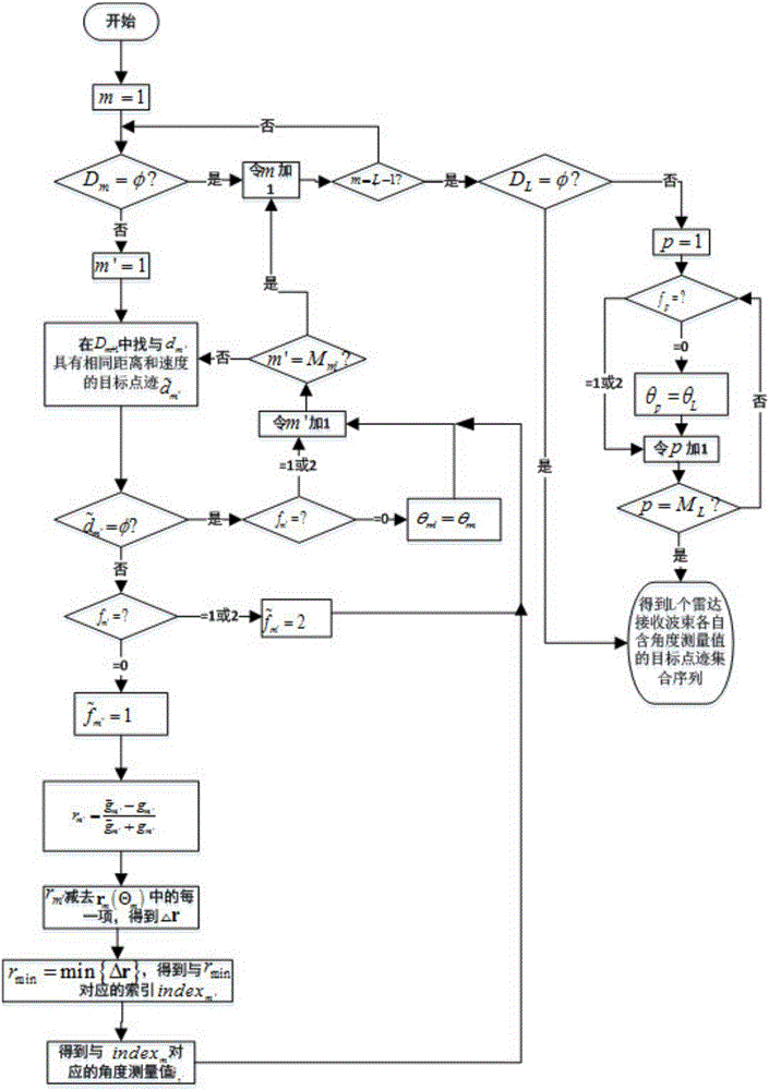
The invention relates to a multi-beam combined angle measuring angle and point trajectory fusion method of MIMO radar targets under orthogonal waveforms. The method includes the following steps that: the geometric model of radars in a Cartesian coordinate system is established, the number N of radar receiving array elements, the number L of radar received beams, and a radar power radiation space-domain range Omega are determined; a detection region corresponding to Omega is uniformly divided into K detection sub-regions, the received composite signals r<k>i(t) of a k-th detection sub-region which adopts the center pointing direction of an i-th radar received beam as a benchmark; conventional detection processing is carried out on the received composite signals r<k>i(t), so that the target detection result set Di of the i-th radar received beam is obtained; the angle measurement values of Mm target point trajectories in a target detection result set Dm of an m-th radar received beam, a target point trajectory set D<~>m containing the angle measurement values of the m-th radar received beam and the target point trajectory set sequence D containing the angle measurement values of L radar received beams are calculated sequentially; and point trajectory fusion is carried out, so that a target point trajectory set final sequence D<^> containing the angle measurement values of the L radar received beams in one coherent processing time is obtained.

Description

technical field [0001] The invention belongs to the field of radar technology, in particular to a multi-beam joint angle measurement and spot fusion method for a MIMO radar target under an orthogonal waveform, that is, a multiple-input multiple-output (Multiple-Input Multiple-Output, MIMO) radar under an orthogonal waveform The multi-beam joint angle measurement and point trace fusion method of the target is suitable for the multi-beam joint angle measurement and point trace fusion of the centralized MIMO radar target under the orthogonal waveform. Background technique [0002] The role of radar in today's and future electronic warfare is irreplaceable. However, due to the rapid development of science and technology, modern radars are faced with threats such as electronic interference, ultra-low altitude penetration, and radiation missiles. Therefore, it is necessary to improve old radars or develop new ones. The radar system can better complete the tasks of target detection...

Claims


Application Information

Patent Timeline
IPC IPC(8): G01S7/292
CPCG01S7/2921
Inventor 苏涛张杏吴凯李强陈艳利
Owner XIDIAN UNIV
Learn More