
A flight control device for an aircraft

A technology of flight control and aircraft, applied in aircraft control, aircraft transmission, aircraft power plant, etc., can solve problems such as complex driving tasks, and achieve the effect of simple recovery of changing force

Active Publication Date: 2016-10-26
SAFRAN ELECTRONICS & DEFENSE
View PDF6 Cites 5 Cited by
  • Summary
  • Abstract
  • Description
  • Claims
  • Application Information

AI Technical Summary

Problems solved by technology

Nevertheless, and especially in the case of convertible aircraft, the pilot does not have to fly the aircraft in the same manner when the aircraft is in the normal phase of flight as when it is in the landing or take-off phases, thereby complicating the piloting task

Method used


Image

  • A flight control device for an aircraft
  • A flight control device for an aircraft
  • A flight control device for an aircraft

Examples


Embodiment Construction

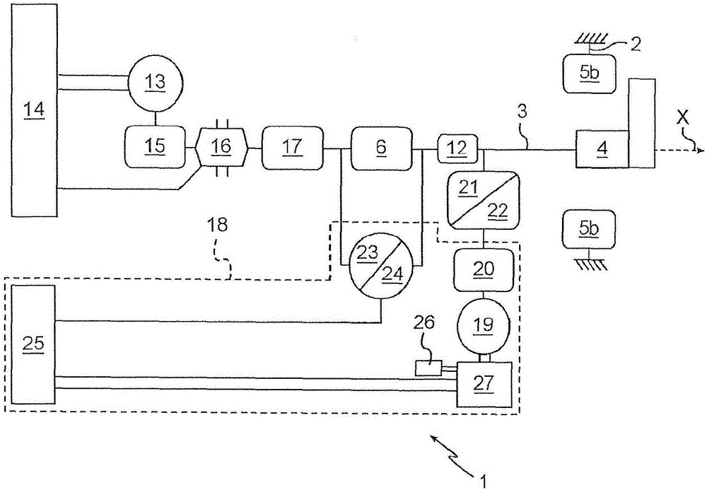
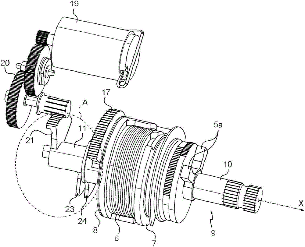
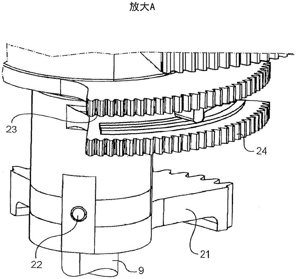
[0024] refer to Figures 1 to 3 , in this example, the flight control device of the invention, generally given the reference number 1 , is mounted on a convertible aircraft.

[0025] The flight control device 1 comprises a base 2 and an operating lever 3 pivotally mounted on the base for pivoting about an axis X of rotation. In this example, a joystick 3 is connected to a control stick 4 of the aircraft for controlling the pitching movement of the aircraft.

[0026] In a known manner, the flight control device 1 has mechanical means for limiting the angular travel of the operating lever about said axis X of rotation. To this end, the operating lever 3 has two abutments 5 a cooperating with two corresponding abutments 5 b of the base 2 to limit the operating lever in a first direction of rotation about the axis X of rotation and in a second direction of rotation angular travel.

[0027] The flight control device 1 also has mechanical means for generating a return force for r...


PUM


Abstract

The invention relates to a flight control device (1) for an aircraft, the device comprising a mount (2), a lever (3) pivotally mounted on the mount, and mechanical means for generating a return force for the lever, said means including a spring (6) and a first motor member (13) that are arranged so that a first end of the spring is constrained to move in rotation with the lever and a second end of the spring is constrained to move in rotation with an outlet shaft of the first motor member. According to the invention, the flight control device includes an electrical assistance system (18) for assisting said mechanical means for generating a return force.

Description

technical field [0001] The invention relates to a flight control device for an aircraft. More particularly but not exclusively, the invention relates to a flight control device for a convertible aircraft, ie an aircraft capable of vertical take-off and landing. Background technique [0002] The flight controls are used to control the movement of the aircraft based on the movements exerted by the pilot on a control stick connected to the flight controls. Nevertheless, and especially in the case of convertible aircraft, the pilot does not have to fly the aircraft in the same way when the aircraft is in a normal flight phase as when it is in a landing or take-off phase, thereby complicating the piloting task. [0003] In order to assist the pilot, it is therefore known to provide a flight control device comprising: a base; an operating lever pivotally mounted on the base to pivot about at least one axis of rotation and designed to be fixed to the control lever of the aircraft...

Claims


Application Information

Patent Timeline
Patent Type & Authority Applications(China)
IPC IPC(8): B64C13/46
CPCB64C13/505B64C13/0421B64C13/341B64C13/345B64C13/507
Inventor B·蒂利N·拉沃克斯
Owner SAFRAN ELECTRONICS & DEFENSE
Learn More