
Device and method for improving azimuth measurement precision in coherent wind finding laser radar

A lidar and coherent wind measurement technology, applied in measurement devices, radio wave measurement systems, mapping and navigation, etc., can solve the problems of low accuracy, limited use, high price, etc., and achieve the effect of improving measurement accuracy and high precision

Active Publication Date: 2016-10-26
江西省智成测控技术研究所有限责任公司
View PDF11 Cites 10 Cited by
  • Summary
  • Abstract
  • Description
  • Claims
  • Application Information

AI Technical Summary

Problems solved by technology

The accuracy of the general compass to measure the azimuth is low, and the measurement accuracy is on the order of degrees
2. The north finder is a high-precision dual-axis power-tuned gyroscope, which can independently determine the true north direction value of the attached carrier by measuring the earth's rotation angular velocity, and is not disturbed and affected by the external magnetic field or other environments; in addition, it It can also be combined with acceleration to measure and correct the horizontal angle. Although the north finder has high precision, it is expensive and its use is limited.

Method used


Image

  • Device and method for improving azimuth measurement precision in coherent wind finding laser radar
  • Device and method for improving azimuth measurement precision in coherent wind finding laser radar
  • Device and method for improving azimuth measurement precision in coherent wind finding laser radar

Examples


Embodiment Construction

[0024] The present invention will be described in further detail below in conjunction with the embodiments and with reference to the accompanying drawings.

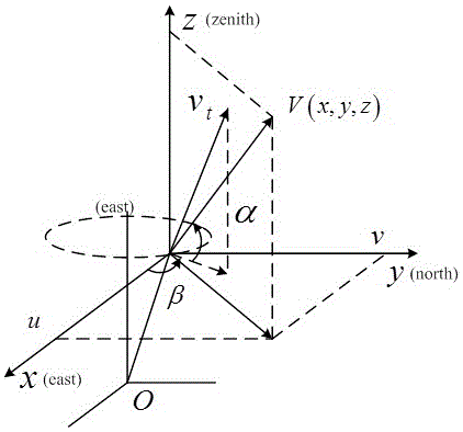
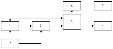
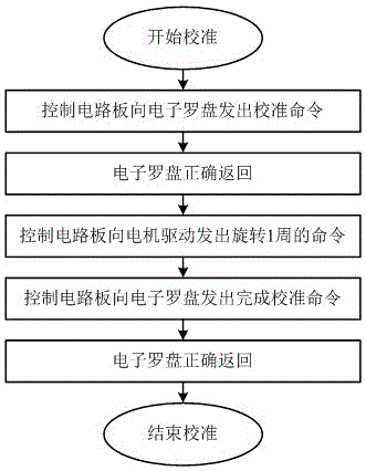
[0025] A device for improving the accuracy of azimuth angle measurement in a coherent wind laser radar, including a control circuit board 1, a motor driver 2, a conductive slip ring 3, a motor 4, a rotating platform 5, an electronic compass 6 and a power supply 7, and the electronic compass 6 and control The circuit board 1, the motor driver 2, the conductive slip ring 3, and the motor 4 are sequentially connected in series to the rotating platform 5, and the power supply 7 supplies power for the control circuit board 1 and the motor driver 2. On the one hand, the control circuit board 1 communicates with the electronic compass 6 to control the electronic compass. The compass 6 realizes magnetic interference calibration and reads the azimuth information of the electronic compass, and on the other hand controls the motor dr...


PUM


Abstract

The invention discloses a device and method for improving azimuth measurement precision in a coherent wind finding laser radar. The method comprises the following steps: at first, calibrating an electronic compass; then under the control of a control circuit board, driving the electronic compass to rotate by a rotary platform, recording the angle of the rotary platform and read azimuth of the electronic compass; preprocessing the azimuth of the electronic compass, fitting the azimuth by a linear least square method, calculating the intercept and slope of the linear functional relationship; and finally according to the angle of the rotary platform, calculating the azimuth. Because the rotary platform adopts a worm and gear structure; a control circuit board and a motor driver are used to obtain an angle, wherein the precision of the angle is higher than electronic compass; and thus the provided device and method can improve the azimuth measuring precision of a coherent wind finding laser radar. Moreover, the device does not need extra equipment or human; only needs the devices in a coherent wind finding laser radar, the precision improvement is automatically performed under the control of an algorithm; the method and device are convenient, fast, and intelligent, and the precision is high.

Description

technical field [0001] The invention relates to the technical field of coherent wind-measuring lidar, in particular to a device and method for improving the accuracy of azimuth angle measurement in coherent wind-measuring lidar. Background technique [0002] As a new active atmospheric remote sensing instrument developed in recent years, coherent wind lidar has the advantages of small size, ability to measure under clear sky conditions, high wind field measurement accuracy, and high temporal and spatial resolution. It has broad application prospects in military and civil fields such as aerospace, remote sensing and telemetry, and meteorological observation. Accidents caused by weather can be used to arrange reasonable aircraft take-off and landing density services for airports; it can also be used for real-time measurement of wind direction and wind speed in antiaircraft artillery positions, providing correction data for weapon system launches, and improving hit rates. In t...

Claims


Application Information

Patent Timeline
Patent Type & Authority Applications(China)
IPC IPC(8): G01C17/32G01S7/48G01S17/95
CPCG01C17/32G01S7/48G01S17/95Y02A90/10
Inventor 贾晓东
Owner 江西省智成测控技术研究所有限责任公司
Learn More